
Main menu

  • Home
  • Content
    • Current
      • JNMT Supplement
    • Ahead of print
    • Past Issues
    • Continuing Education
    • JNMT Podcast
    • SNMMI Annual Meeting Abstracts
  • Subscriptions
    • Subscribers
    • Rates
    • Journal Claims
    • Institutional and Non-member
  • Authors
    • Submit to JNMT
    • Information for Authors
    • Assignment of Copyright
    • AQARA Requirements
  • Info
    • Reviewers
    • Permissions
    • Advertisers
    • Corporate & Special Sales
  • About
    • About Us
    • Editorial Board
    • Contact Information
  • More
    • Alerts
    • Feedback
    • Help
    • SNMMI Journals
  • SNMMI
    • JNMT
    • JNM
    • SNMMI Journals
    • SNMMI

User menu

  • Subscribe
  • My alerts
  • Log in
  • Log out
  • My Cart

Search

  • Advanced search
Journal of Nuclear Medicine Technology
  • SNMMI
    • JNMT
    • JNM
    • SNMMI Journals
    • SNMMI
  • Subscribe
  • My alerts
  • Log in
  • Log out
  • My Cart
Journal of Nuclear Medicine Technology

Advanced Search

  • Home
  • Content
    • Current
    • Ahead of print
    • Past Issues
    • Continuing Education
    • JNMT Podcast
    • SNMMI Annual Meeting Abstracts
  • Subscriptions
    • Subscribers
    • Rates
    • Journal Claims
    • Institutional and Non-member
  • Authors
    • Submit to JNMT
    • Information for Authors
    • Assignment of Copyright
    • AQARA Requirements
  • Info
    • Reviewers
    • Permissions
    • Advertisers
    • Corporate & Special Sales
  • About
    • About Us
    • Editorial Board
    • Contact Information
  • More
    • Alerts
    • Feedback
    • Help
    • SNMMI Journals
  • Watch or Listen to JNMT Podcast
  • Visit SNMMI on Facebook
  • Join SNMMI on LinkedIn
  • Follow SNMMI on Twitter
  • Subscribe to JNMT RSS feeds
Research ArticleImaging

Geometric Calibration and Image Reconstruction for a Segmented Slant-Hole Stationary Cardiac SPECT System

Yanfei Mao, Zhicong Yu and Gengsheng L. Zeng
Journal of Nuclear Medicine Technology June 2015, 43 (2) 103-112; DOI: https://doi.org/10.2967/jnmt.114.153668
Yanfei Mao
1Utah Center for Advanced Imaging Research (UCAIR), Department of Radiology, University of Utah, Salt Lake City, Utah
2Department of Bioengineering, University of Utah, Salt Lake City, Utah
  • Find this author on Google Scholar
  • Find this author on PubMed
  • Search for this author on this site
Zhicong Yu
3Department of Radiology, Mayo Clinic, Rochester, Minnesota; and
  • Find this author on Google Scholar
  • Find this author on PubMed
  • Search for this author on this site
Gengsheng L. Zeng
1Utah Center for Advanced Imaging Research (UCAIR), Department of Radiology, University of Utah, Salt Lake City, Utah
4Department of Engineering, Weber State University, Ogden, Utah
  • Find this author on Google Scholar
  • Find this author on PubMed
  • Search for this author on this site
  • Article
  • Figures & Data
  • Supplemental
  • Info & Metrics
  • PDF
Loading

Article Figures & Data

Figures

  • Tables
  • Additional Files
  • FIGURE 1.
    • Download figure
    • Open in new tab
    • Download powerpoint
    FIGURE 1.

    Illustration of proposed 7-segment slant-hole collimator. Projection is elongated at outer sections. Dashed ellipses represent projection on that section of detector when sphere is placed at rotation center.

  • FIGURE 2.
    • Download figure
    • Open in new tab
    • Download powerpoint
    FIGURE 2.

    Cross section of common volume (CV) in x,y-plane.
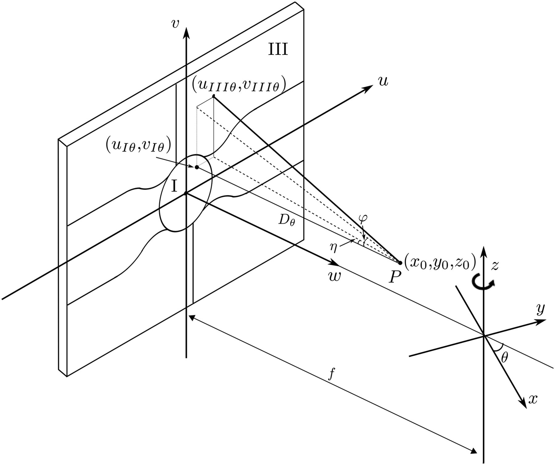
  • FIGURE 3.
    • Download figure
    • Open in new tab
    • Download powerpoint
    FIGURE 3.

    Definition of slant angles η and φ, detector coordinates, and object coordinates. z-axis is rotation axis of detector.

  • FIGURE 4.
    • Download figure
    • Open in new tab
    • Download powerpoint
    FIGURE 4.

    Setup of point source P.
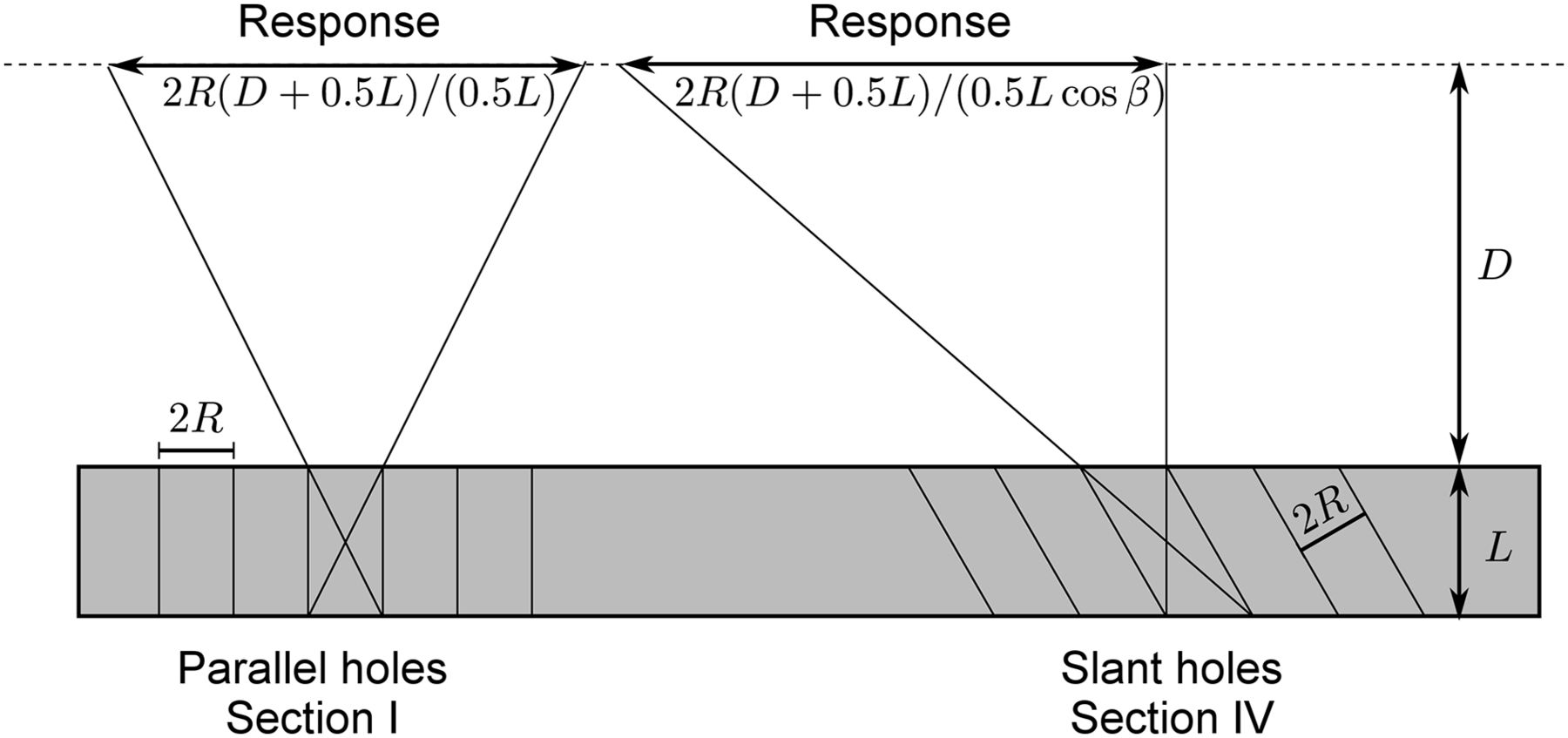
  • FIGURE 5.
    • Download figure
    • Open in new tab
    • Download powerpoint
    FIGURE 5.

    Illustration of geometric response for parallel holes and slant holes.

  • FIGURE 6.
    • Download figure
    • Open in new tab
    • Download powerpoint
    FIGURE 6.

    Close-up diagram of footprint of point response function with respect to slant angles α and β.
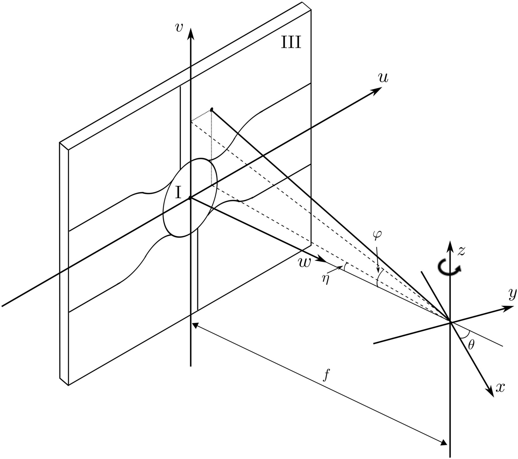
  • FIGURE 7.
    • Download figure
    • Open in new tab
    • Download powerpoint
    FIGURE 7.

    Reconstruction results of point source without (left) and with (right) blurring correction. Five and 50 iterations were used, respectively.
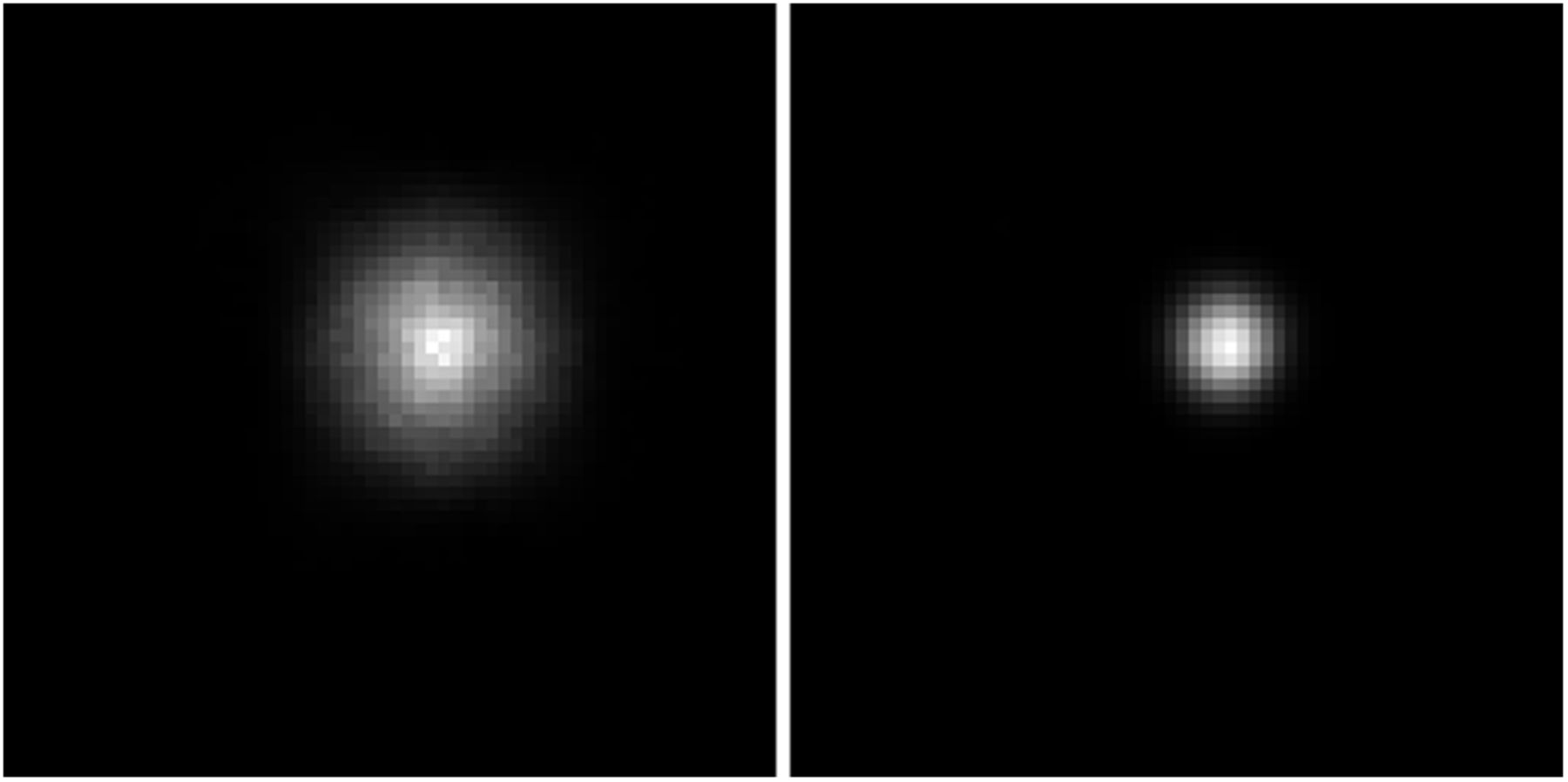
  • FIGURE 8.
    • Download figure
    • Open in new tab
    • Download powerpoint
    FIGURE 8.

    Reconstruction results of 2 point sources at 50 iterations. Left one was reconstructed with true parameters. Right one was reconstructed with estimated parameters. Blurring correction was applied in both images.

  • FIGURE 9.
    • Download figure
    • Open in new tab
    • Download powerpoint
    FIGURE 9.

    rojection of point source at 90°.

  • FIGURE 10.
    • Download figure
    • Open in new tab
    • Download powerpoint
    FIGURE 10.

    Reconstruction results of point source. From left to right: without calibration, with joint estimation calibration but no blurring correction, with joint estimation calibration and blurring correction. Sixty iterations were applied.

  • FIGURE 11.
    • Download figure
    • Open in new tab
    • Download powerpoint
    FIGURE 11.

    Projection of heart phantom at 0° and 90°.
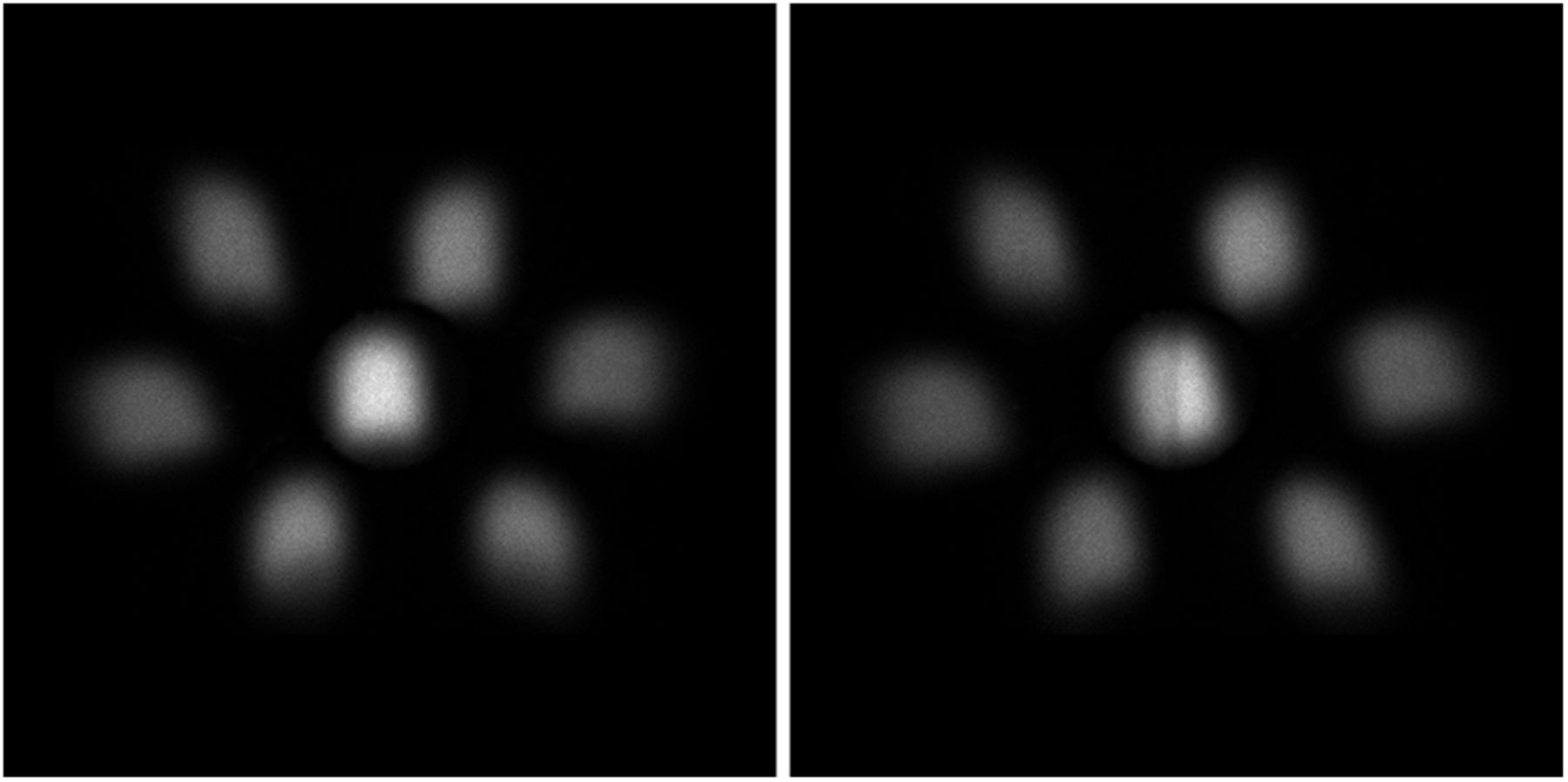
  • FIGURE 12.
    • Download figure
    • Open in new tab
    • Download powerpoint
    FIGURE 12.

    Reconstruction results of heart phantom without calibration (top), with calibration but no blurring correction(middle), and with calibration and blurring correction (bottom). From left to right: vertical long-axis, short-axis, and horizontal long-axis cuts. All images were reconstructed at 80 iterations.
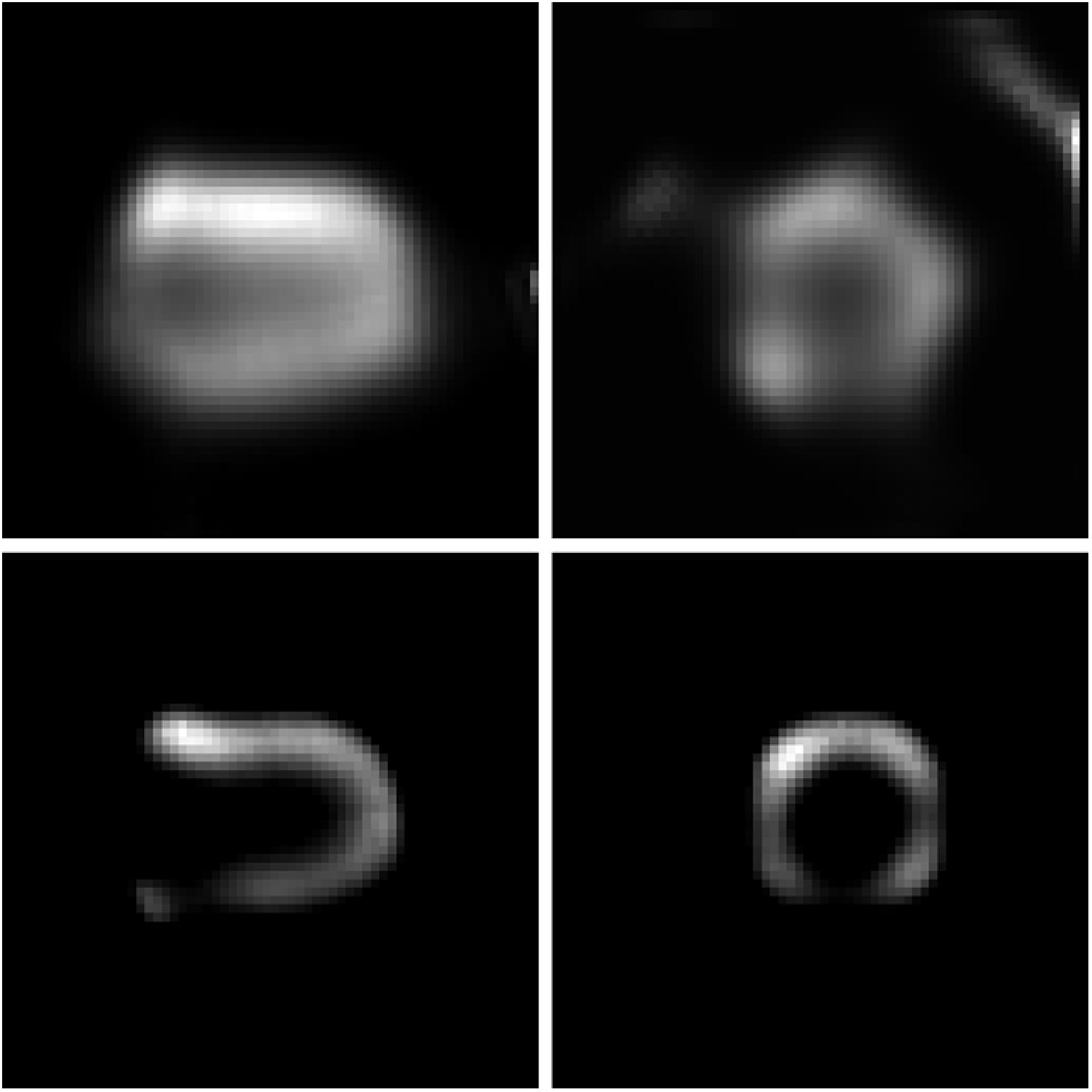
  • FIGURE 13.
    • Download figure
    • Open in new tab
    • Download powerpoint
    FIGURE 13.

    Slices showing defect before (top) and after (bottom) calibration. VLA cut is on left, SA cut on right. Blurring correction was applied. All images were scaled to [0 255] and were displayed using the same scale. Image contrast was enhanced for better visualization of defect. A color version of this figure is available as a supplemental file at http://tech.snmjournals.org.

Tables

  • Figures
  • Additional Files
    • View popup
    TABLE 1

    System Parameters

    ParameterData
    Isotope 99mTc
    Activity3 MBq
    Energy window15%
    Hole shapeHexagon
    Hole diameter1.9 mm
    Septal thickness0.3 mm
    Rotation radius f 266.5 mm
    ηII −25.7°
    ηIII 12.9°
    ηIV 35.0°
    ηV −35.0°
    ηVI −12.9°
    ηVII 25.7°
    φII 22.0°
    φIII 24.5°
    φIV 6.1°
    φV −6.1°
    φVI −24.5°
    φVII −22.0°
    • View popup
    TABLE 2

    Collimator Information Provided by Manufacturer

    Section no.Slant angle β (deg)Septum length (mm)
    II and VII2516.6
    III and VI22.3516.22
    IV and V2817
    I015
    • View popup
    TABLE 3

    Independently Estimated Parameters with Point Source off Rotation Axis

    Section no.Estimated η (deg)η-error (%)Estimated f (mm)Estimated φ (deg)φ-error (%)Estimated f (mm)
    II−27.25.8250.921.90.5266.5
    III13.76.2253.124.81.2261.8
    IV35.92.6259.87.116.4226.2
    V−35.82.3260.3−6.33.3256.3
    VI−13.65.4251.7−24.81.2261.9
    VII25.70.0267.0−22.00.0265.1
    f (mm)256.7 ± 11.1
    • View popup
    TABLE 4

    Jointly Estimated Parameters, Giving Improved Results

    Section no.Estimated η (deg)η-error (%)Estimated φ (deg)φ-error (%)Estimated f (mm) f-error (%)
    II−25.80.422.10.5265.50.4
    III12.90.024.60.4265.50.4
    IV35.10.36.10.0265.50.4
    V−35.10.3−6.10.0265.50.4
    VI−12.90.0−24.60.4265.50.4
    VII25.80.4−22.10.5265.50.4
    • View popup
    TABLE 5

    Parameters for Segmented Slant-Hole Collimator Obtained from Calibration

    Section no.Independent estimated η (deg)Independent estimated f (mm)Independent estimated φ (deg)Independent estimated f (mm)Joint estimated η (deg)Joint estimated φ (deg)Joint estimated f (mm)
    II−24.6285.529.3239.2−28.1 ± 0.228.1 ± 0.2249.2 ± 2
    III17.6233.129.2242.316.1 ± 0.127.7 ± 0.2249.2 ± 2
    IV42.2240.45.2245.739.6 ± 0.24.4 ± 0.1249.2 ± 2
    V−38.7253.9−3.7255.0−39.6 ± 0.2−4.4 ± 0.1249.2 ± 2
    VI−14.8257.1−28.2224.7−16.1 ± 0.1−27.7 ± 0.2249.2 ± 2
    VII29.8239.7−29.1228.128.1 ± 0.2−28.1 ± 0.2249.2 ± 2

Additional Files

  • Figures
  • Tables
  • Supplemental Data

    Files in this Data Supplement:

    • Supplemental Data
PreviousNext
Back to top

In this issue

Journal of Nuclear Medicine Technology: 43 (2)
Journal of Nuclear Medicine Technology
Vol. 43, Issue 2
June 1, 2015
  • Table of Contents
  • About the Cover
  • Index by author
Print
Download PDF
Article Alerts
Sign In to Email Alerts with your Email Address
Email Article

Thank you for your interest in spreading the word on Journal of Nuclear Medicine Technology.

NOTE: We only request your email address so that the person you are recommending the page to knows that you wanted them to see it, and that it is not junk mail. We do not capture any email address.

Enter multiple addresses on separate lines or separate them with commas.
Geometric Calibration and Image Reconstruction for a Segmented Slant-Hole Stationary Cardiac SPECT System
(Your Name) has sent you a message from Journal of Nuclear Medicine Technology
(Your Name) thought you would like to see the Journal of Nuclear Medicine Technology web site.
Citation Tools
Geometric Calibration and Image Reconstruction for a Segmented Slant-Hole Stationary Cardiac SPECT System
Yanfei Mao, Zhicong Yu, Gengsheng L. Zeng
Journal of Nuclear Medicine Technology Jun 2015, 43 (2) 103-112; DOI: 10.2967/jnmt.114.153668

Citation Manager Formats

  • BibTeX
  • Bookends
  • EasyBib
  • EndNote (tagged)
  • EndNote 8 (xml)
  • Medlars
  • Mendeley
  • Papers
  • RefWorks Tagged
  • Ref Manager
  • RIS
  • Zotero
Share
Geometric Calibration and Image Reconstruction for a Segmented Slant-Hole Stationary Cardiac SPECT System
Yanfei Mao, Zhicong Yu, Gengsheng L. Zeng
Journal of Nuclear Medicine Technology Jun 2015, 43 (2) 103-112; DOI: 10.2967/jnmt.114.153668
Twitter logo Facebook logo LinkedIn logo Mendeley logo
  • Tweet Widget
  • Facebook Like
  • Google Plus One
Bookmark this article

Jump to section

  • Article
    • Abstract
    • MATERIALS AND METHODS
    • RESULTS
    • DISCUSSION
    • CONCLUSION
    • APPENDIX A
    • APPENDIX B
    • DISCLOSURE
    • Acknowledgments
    • Footnotes
    • REFERENCES
  • Figures & Data
  • Supplemental
  • Info & Metrics
  • PDF

Related Articles

  • PubMed
  • Google Scholar

Cited By...

  • No citing articles found.
  • Google Scholar

More in this TOC Section

  • Early 10-Minute Postinjection [18F]F-FAPI-42 uEXPLORER Total-Body PET/CT Scanning Protocol for Staging Lung Cancer Using HYPER Iterative Reconstruction
  • Single- Versus Dual-Time-Point Imaging for Transthyretin Cardiac Amyloid Using 99mTc-Pyrophosphate
  • Does Arthrography Improve Accuracy of SPECT/CT for Diagnosis of Aseptic Loosening in Patients with Painful Knee Arthroplasty: A Systematic Review and Metaanalysis
Show more Imaging

Similar Articles

Keywords

  • Geometric calibration
  • cardiac single photon emission computed tomography (SPECT)
  • collimator
  • slant-hole
SNMMI

© 2025 SNMMI

Powered by HighWire