


Abstract
The use of convergent-beam SPECT can increase detection sensitivity; however, the projection data are likely to be truncated if the patient is not properly positioned. This article describes a patient-positioning method that has been adopted in our hospital for cardiac SPECT scans when convergent-beam collimators are used. Methods: The system that we use has 3 detector heads and a patient table (i.e., bed) with 3 locking positions: left, center, and right. When convergent-beam collimators are used in a cardiac SPECT scan, the patient table is locked in the left position, and a noncircular contour orbit is set up. Results: We were able to acquire truncation-free cardiac projections for all of our patients. Conclusion: Patient positioning in convergent-beam SPECT is important. If the patient is not positioned properly, then the heart may be truncated in some projection views. The use of the left locking position of the patient table positions the heart at the center of rotation, and the heart is not truncated in the projection data.
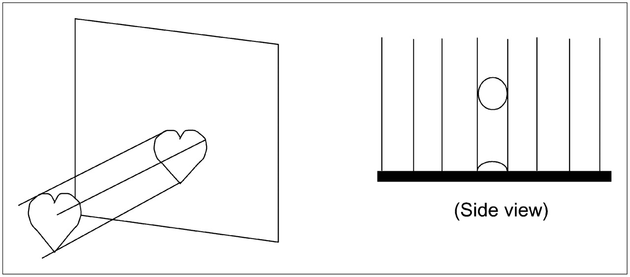
SPECT imaging of a small organ, for example, the heart, wastes detector area when parallel-hole collimators are used (Fig. 1), especially when the detector area is large.

When parallel-hole collimators are used to image heart, detector area is not efficiently used, especially when detector area is large.
Various focusing collimators have been developed to better use the detector area, as shown in Figure 2. The most popular ones are fanbeam, conebeam, varying-focal-length, parallel-slant-hole, and pinhole collimators (1–7). These collimators can potentially increase photon detection efficiency and provide more photon counts for the organ of interest.

Convergent-beam collimators can magnify image size on detector or generate multiple images of object on detector, so that large detector area is more efficiently used for imaging of small organs. (Left) Fanbeam collimator. (Middle) Combined parallel-hole and slant-hole collimator. (Right) Collimator with varying focal length.
A major drawback of using focusing collimators is the difficulty in positioning the patient so that the organ of interest always stays in the field of view of the detector as the detector rotates. When the organ is not in the field of view for some detector view angles, the projections of the organ are considered to be truncated, and the advantage of using a focusing collimator is lost.
In order to make convergent-beam collimation imaging work effectively, the organ of interest must be positioned at the center of detector rotation. The goal of this study was to provide a practical patient-positioning technique for cardiac SPECT.
MATERIALS AND METHODS
Patient Table Translation Method for Ordinary SPECT Systems
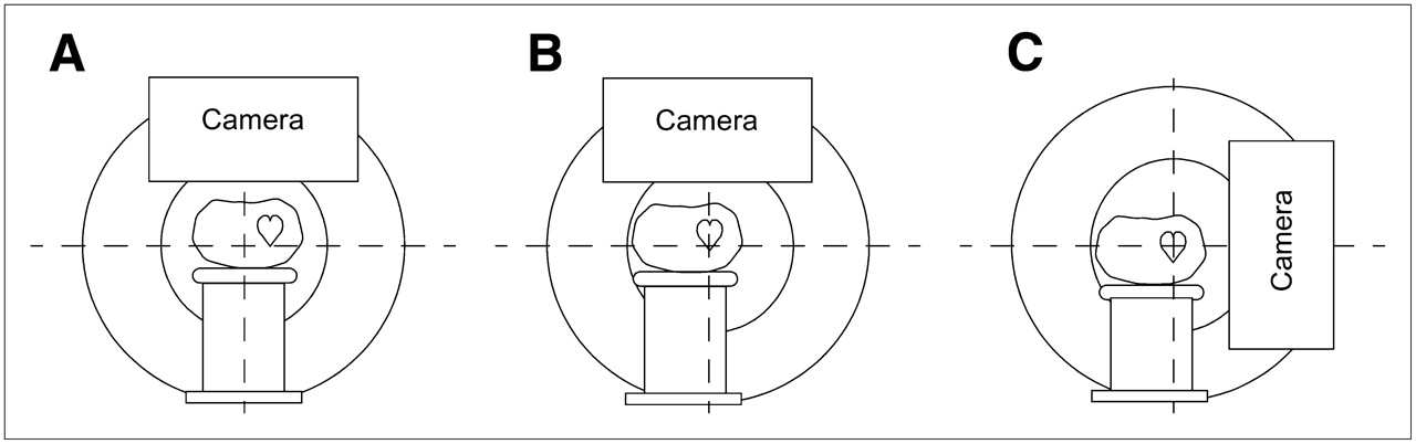
In current commercial SPECT systems, there are 3 patient table (i.e., bed) locking positions: left, center, and right. For normal SPECT scans, the patient table is locked in the center position. Our experience (8–11) suggests that the patient table should be locked in the left position for cardiac scans when convergent-beam collimators are used (Fig. 3). In our hospital, we use this method with a Picker triple-head PRISM 3000XP system (Philips Medical Systems). The detailed procedure is as follows.

Patient-positioning procedure. (A) Default patient table position, in which table is centered. (B) Suggested left locking position of patient table. Top-view camera is used to monitor whether heart is centered. (C) Adjustment of table height so that heart is at center of side-view camera.
Step 1.
Lock the patient table in the left position, as shown in Figure 3B.
Step 2.
The patient should lie down on the table in a head-first position, facing up. (If the patient faces down, the table should be locked in the right position.) Rotate the camera to the 12 o'clock position. Translate the table “in” so that the heart is at the center of the camera axially, as indicated on a camera display.
Step 3.
The patient's heart should be almost centered on that camera. An optional step is to instruct the patient to move to the left or right a little until the patient's heart is seen exactly at the center of the camera on the patient setup monitor.
Step 4.
For a single-head system, rotate the camera to the 3 o'clock or 9 o'clock position. For a multihead system, rotation is not necessary; simply position another head at the 3 o'clock or 9 o'clock position.
Step 5.
Adjust the table height so that the heart is at the center of the side-view camera.
Step 6.
Set up a standard circular orbit or noncircular contour orbit.
Detector Head Translation Method for Modern SPECT Systems
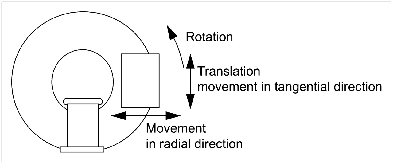
We also suggest another method, in which the left locking position of the patient table is not necessary. This method takes advantage of the ability of state-of-the-art SPECT detectors to translate in the tangential direction, in addition to rotating and moving in and out (Fig. 4).

In modern SPECT systems, detector head can rotate and move radially and tangentially.
This method eliminates the step of offsetting the patient table. Once the patient is initially positioned, the detector head translation at each camera view angle can be automatically calculated so that the heart is always at the center of the field of view. The detailed procedure is as follows.
Step 1.
The patient should lie down on the table, which is in the center locking position. Translate the table “in” so that the heart is at the center of the camera axially. Adjust the table height so that the heart is approximately at the level of the center of rotation. This initial setup can be readily monitored on a side-view camera (similar to the situation shown in Fig. 3C).
Step 2 (for a Multihead SPECT System).
On the computer screen, the technologist is able see the projection images on all detectors. The technologist uses a mouse click to mark the center of the heart on projection images for all heads. The computer calculates the center (xh, yh) of the heart. The center (xh, yh) is obtained by solving a set of linear equations, which are set up by considering the imaging geometry of the multidetector views.
Step 2 (for a Single-Head SPECT System).
On the computer screen, the technologist is able to see the projection image on the detector. The technologist uses a mouse click to mark the center of the heart on the projection image, rotates the detector to a different angle, and marks the center of the heart again. The computer calculates the center (xh, yh) of the heart. The center (xh, yh) is obtained by solving a set of linear equations, which are set up by considering the imaging geometry of these 2 views.
Step 3.
Set up the circular or noncircular detector orbit as usual. At this step, the translation of the detector is calculated by the computer so that the center of the detector always points directly to the center of the heart (xh, yh), as shown in Figure 5. The translation calculation method is described in the next section.
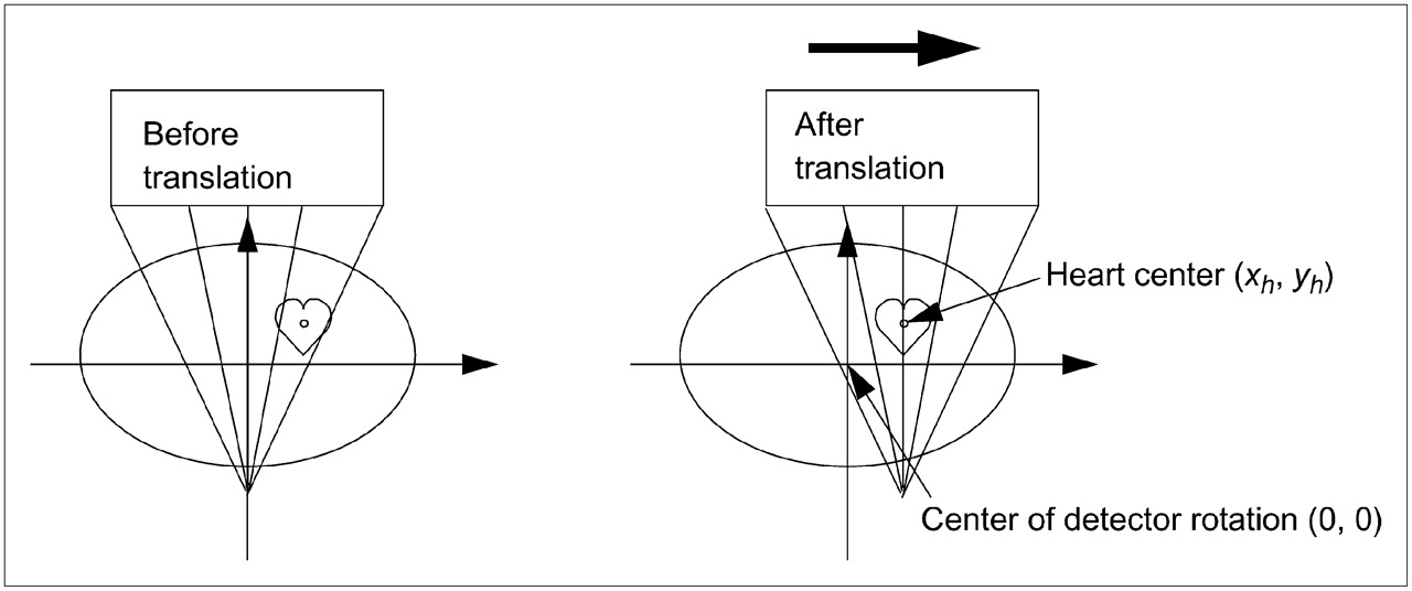
In modern SPECT systems, detector head can translate at each view, so that central ray passes through center of heart.
Translation Calculation for Fanbeam Imaging
This section provides the equations that are required to calculate the amount of detector head translation at each detector view angle for modern SPECT systems. In Figure 6, the fanbeam detector is at angle θ. During patient setup, the technologist marks tθ as the center of the organ on the detector. The fanbeam focal point location is (xθ, yθ) = (−rθ cosθ, −rθ sinθ), where rθ is the distance from the center of rotation and the focal point. The fanbeam focal length (i.e., the distance from the focal point to the detector) is F. We define αθ = tan−1 (tθ/F) to be the angle between a projection ray (labeled as tθ on the detector) and the central fanbeam ray.
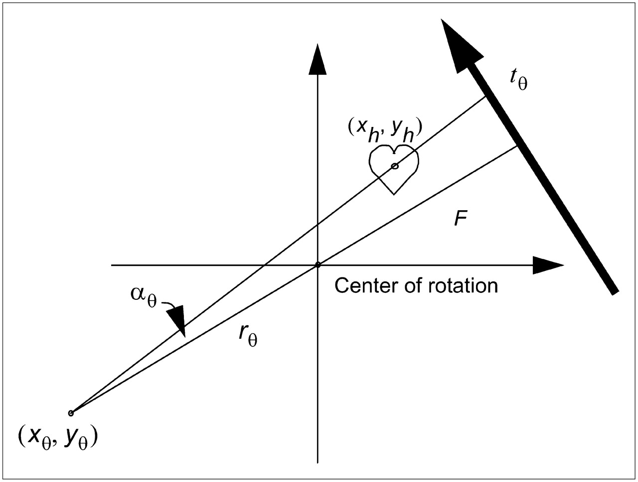
Coordinate system for fanbeam imaging geometry. During patient setup, center of heart on detector is marked as tθ and stored in computer. Two angles of θ are required to determine center of heart.
The center of the heart (xh, yh) can be expressed as Eq. 1and
 Eq. 2for a certain parameter λ. Therefore, if one marks the center of the heart at 2 different detector positions, θ1 and θ2, then
 Eq. 3and
 Eq. 4from which one can easily obtain λ1 and λ2 and, hence, (xh, yh).
Once the coordinates of the heart (xh, yh) are determined, the amount of translation tθ at any detector view angle θ can be calculated as Eq. 5
Eq. 5
Focal Length and Orbit Considerations
In our hospital, the focal length of convergent-beam collimators has been chosen to be 65 cm. If the heart is positioned at the center of rotation, we do not observe truncation of the heart for patients weighing no more than 135 kg (300 lb). The worst-case situation is shown in Figure 7A: the detector is at an angle at which the distance from the detector to the heart is the largest. If the heart is not truncated in this worst-case situation, then a circular scanning orbit should be safe to use, and the heart should not be truncated. Better practice is to use a noncircular contour orbit, which can produce better resolution. If the heart is not positioned exactly at the center, then the use of a noncircular contour orbit can significantly reduce the risk of data truncation of the heart. We have found that a 65-cm focal length is easy to work with during setup for patients weighing no more than 135 kg.
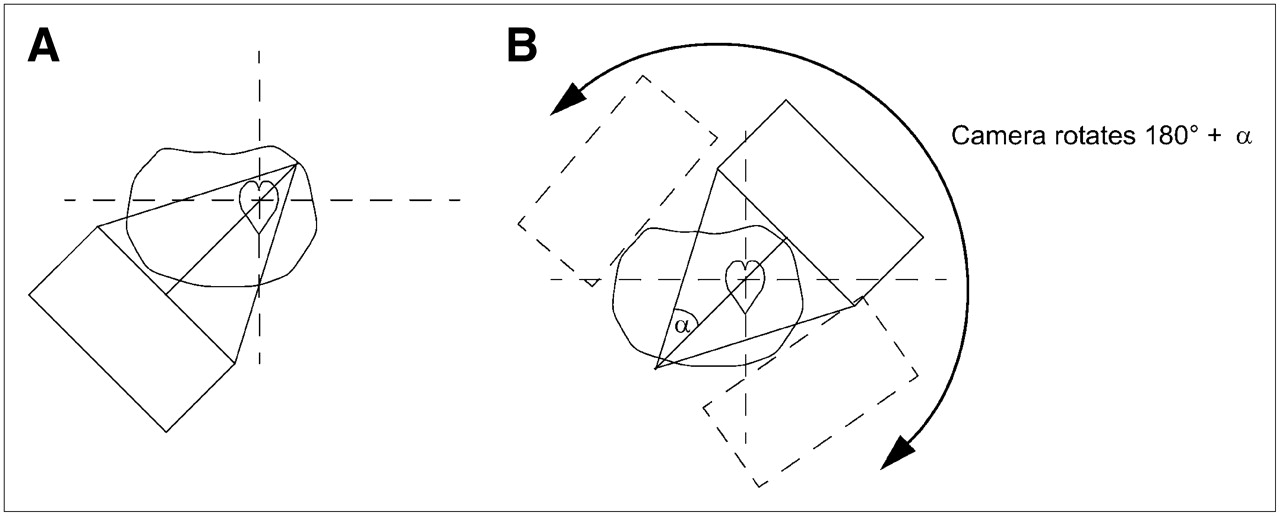
(A) Worst-case situation, at which truncation of heart is most likely to happen. (B) For patients weighing more than 135 kg, short scan can be used to avoid worst-case situation.
For patients weighing more than 135 kg (300 lb), convergent-beam collimators can still be used by substituting a short scan instead of a 360° full scan. In a short scan, the camera rotates 180° plus half of the collimator fanbeam angle, and within this angular range, the camera is close to the heart, as shown in Figure 7B. Scanning the patient at least 180° plus half of the collimator fanbeam angle α guarantees the acquisition of a complete dataset for fanbeam imaging geometry (12).
RESULTS AND DISCUSSION
The use of convergent-beam (e.g., fanbeam or conebeam) collimators in SPECT for imaging a small organ such as the heart increases detection sensitivity 2- to 3-fold (11). Unfortunately, convergent-beam collimators are not commonly used in clinics because of the likelihood of producing truncated projection data.
Here we described a method involving a left locking position of the patient table for cardiac SPECT with convergent-beam collimators. We have used this method to perform cardiac SPECT for more than 200 patients in our hospital. We have found that when the collimator focal length is 65 cm, then all cardiac scans can be performed without data truncation of the heart. For patients weighing more than 135 kg, a short scan is suggested. We must point out that table-shifting capability is vendor dependent; some SPECT systems do not have this capability.
We also described a patient-positioning method for modern SPECT scanners, in which the detector heads can translate tangentially. For these new systems, patient positioning can be achieved automatically without the left locking maneuver.
The left locking method is routine practice in our hospital, and we share this method with the SPECT community so that convergent-beam collimators can be more widely used. The detector head translation method is our vision for the future; it has not been implemented by manufacturers yet. The latter method will be more user-friendly once it becomes available.
CONCLUSION
If convergent-beam collimators can be widely applied, the resultant more-than-2-fold gain in detection sensitivity has the potential to reduce patient scanning time by half. Such an achievement is significant in terms of cost-effective patient care.
Acknowledgments
We thank Dr. Roy Rowley for English editing of this article.
Footnotes
-
COPYRIGHT © 2007 by the Society of Nuclear Medicine, Inc.
References
- Received for publication February 22, 2007.
- Accepted for publication April 12, 2007.


Jump to section
Related Articles
Cited By...
- No citing articles found.