
Main menu

  • Home
  • Content
    • Current
      • JNMT Supplement
    • Ahead of print
    • Past Issues
    • SNMMI Annual Meeting Abstracts
  • Subscriptions
    • Subscribers
    • Rates
    • Journal Claims
    • Institutional and Non-member
  • Authors
    • Submit to JNMT
    • Information for Authors
    • Assignment of Copyright
    • AQARA Requirements
  • Info
    • Permissions
    • Continuing Education
    • Advertisers
    • Corporate & Special Sales
  • About
    • About Us
    • Editorial Board
    • Editorial Contact
  • More
    • Alerts
    • Feedback
    • Help
    • SNMMI Journals
  • SNMMI
    • JNMT
    • JNM
    • SNMMI Journals
    • SNMMI

User menu

  • Subscribe
  • My alerts
  • Log in
  • My Cart

Search

  • Advanced search
Journal of Nuclear Medicine Technology
  • SNMMI
    • JNMT
    • JNM
    • SNMMI Journals
    • SNMMI
  • Subscribe
  • My alerts
  • Log in
  • My Cart
Journal of Nuclear Medicine Technology

Advanced Search

  • Home
  • Content
    • Current
    • Ahead of print
    • Past Issues
    • SNMMI Annual Meeting Abstracts
  • Subscriptions
    • Subscribers
    • Rates
    • Journal Claims
    • Institutional and Non-member
  • Authors
    • Submit to JNMT
    • Information for Authors
    • Assignment of Copyright
    • AQARA Requirements
  • Info
    • Permissions
    • Continuing Education
    • Advertisers
    • Corporate & Special Sales
  • About
    • About Us
    • Editorial Board
    • Editorial Contact
  • More
    • Alerts
    • Feedback
    • Help
    • SNMMI Journals
  • Follow SNMMI on Twitter
  • Visit SNMMI on Facebook
  • Join SNMMI on LinkedIn
  • Subscribe to JNMT RSS feeds
Research ArticleContinuing Education

PET/MRI, Part 3: Protocols and Procedures

Elad Nevo, Peter Kamvosoulis and Geoff Currie
Journal of Nuclear Medicine Technology March 2022, 50 (1) 17-24; DOI: https://doi.org/10.2967/jnmt.121.262544
Elad Nevo
1Department of Radiology, Lucille Packard Children’s Hospital, Stanford University, Palo Alto, California;
  • Find this author on Google Scholar
  • Find this author on PubMed
  • Search for this author on this site
Peter Kamvosoulis
2Magnetic Resonance Department, New York–Presbyterian/Weill Cornell Medical Center, New York, New York;
  • Find this author on Google Scholar
  • Find this author on PubMed
  • Search for this author on this site
Geoff Currie
3School of Dentistry and Health Science, Charles Sturt University, Wagga Wagga, New South Wales, Australia; and
4Department of Radiology, Baylor College of Medicine, Houston, Texas
  • Find this author on Google Scholar
  • Find this author on PubMed
  • Search for this author on this site
  • Article
  • Figures & Data
  • Info & Metrics
  • PDF
Loading

Article Figures & Data

Figures

  • FIGURE 1.
    • Download figure
    • Open in new tab
    • Download powerpoint
    FIGURE 1.

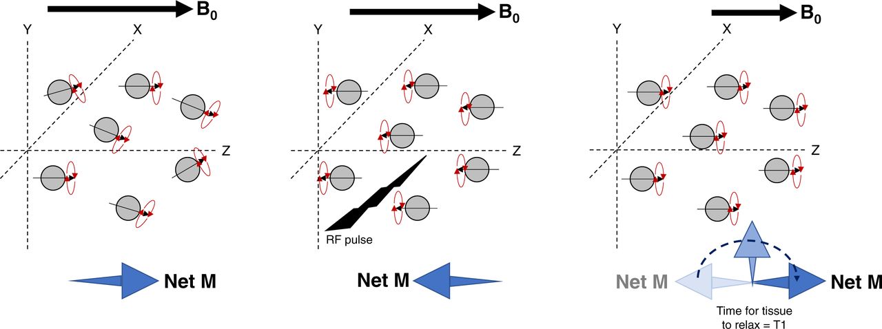
    Schematic representation of T1 signal produced by longitudinal relaxation. Proton dipoles have net magnetism in magnetic field (left) but become aligned after radiofrequency pulse (middle) and produce T1 signal on relaxation (right). B0 = magnetic field; M = magnetism; RF = radiofrequency.

  • FIGURE 2.
    • Download figure
    • Open in new tab
    • Download powerpoint
    FIGURE 2.

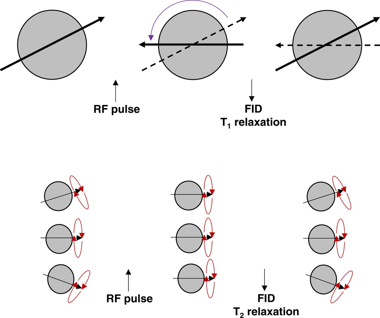
    Schematic representation of difference between T1 (top) and T2 (bottom) signal production. For T1, proton dipoles become aligned after radiofrequency pulse and produce T1 signal on relaxation. T2 signals relate to precession of proton dipoles relaxing back to ground state. FID = free induction decay; RF = radiofrequency.

  • FIGURE 3.
    • Download figure
    • Open in new tab
    • Download powerpoint
    FIGURE 3.

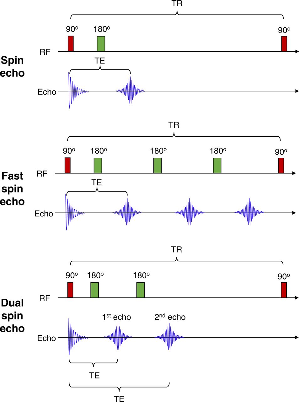
    Schematic representation of MR sequences. Spin echo uses 90° followed by 180° radiofrequency pulse to produce echo. Fast spin echo uses 90° followed by multiple 180° radiofrequency pulse to produce multiple echoes. Dual spin echo, as name suggests, produces 2 echoes from 90° followed by repeated 180° radiofrequency pulse. TE = echo time; TR = repetition time.
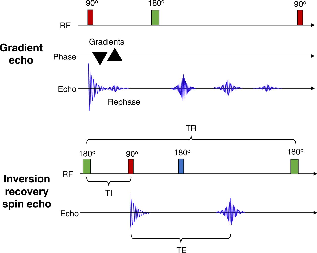
  • FIGURE 4.
    • Download figure
    • Open in new tab
    • Download powerpoint
    FIGURE 4.

    (Top) Schematic representation of GRE in which 90° radiofrequency pulse is followed by bipolar gradients first dephasing free induction decay and then rephasing free induction decay. (Bottom) Schematic representation of inversion recovery spin echo in which 180° radiofrequency pulse is followed by 90° radiofrequency pulse. RF = radiofrequency; TE = echo time; TR = repetition time.
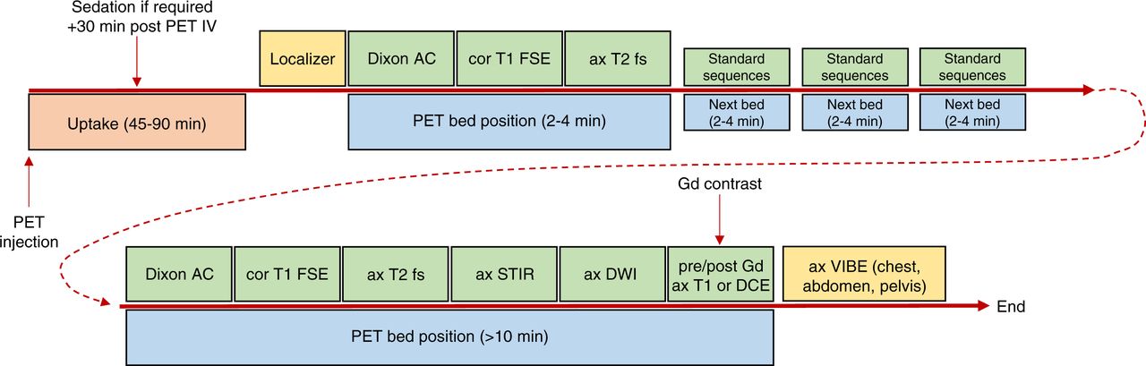
  • FIGURE 5.
    • Download figure
    • Open in new tab
    • Download powerpoint
    FIGURE 5.

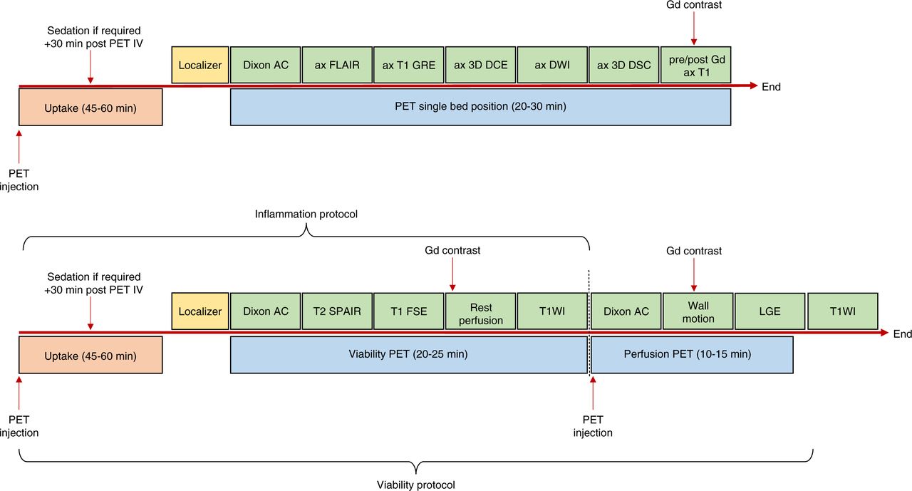
    Flowchart of example of PET/MRI sequence used for whole-body oncology studies. 3D = 3-dimensional; AC = attenuation correction; ax = axial; cor = coronal; DCE = dynamic contrast-enhanced; DSC = dynamic susceptibility contrast; fs = fat saturation; FSE = fast spin echo; Gd = gadolinium; IV = intravenous injection; LGE = late gadolinium enhancement; SPAIR = spectral attenuated inversion recovery; T1WI = T1-weighted imaging.

  • FIGURE 6.
    • Download figure
    • Open in new tab
    • Download powerpoint
    FIGURE 6.

    Flowchart of example of PET/MRI sequence used for brain studies (top) and cardiac studies (bottom). 3D = 3-dimensional; AC = attenuation correction; ax = axial; DCE = dynamic contrast-enhanced; DSC = dynamic susceptibility contrast; FSE = fast spin echo; Gd = gadolinium; IV = intravenous injection; LGE = late gadolinium enhancement; SPAIR = spectral attenuated inversion recovery; T1WI = T1-weighted imaging.

PreviousNext
Back to top

In this issue

Journal of Nuclear Medicine Technology: 50 (1)
Journal of Nuclear Medicine Technology
Vol. 50, Issue 1
March 1, 2022
  • Table of Contents
  • About the Cover
  • Index by author
  • Complete Issue (PDF)
Print
Download PDF
Article Alerts
Sign In to Email Alerts with your Email Address
Email Article

Thank you for your interest in spreading the word on Journal of Nuclear Medicine Technology.

NOTE: We only request your email address so that the person you are recommending the page to knows that you wanted them to see it, and that it is not junk mail. We do not capture any email address.

Enter multiple addresses on separate lines or separate them with commas.
PET/MRI, Part 3: Protocols and Procedures
(Your Name) has sent you a message from Journal of Nuclear Medicine Technology
(Your Name) thought you would like to see the Journal of Nuclear Medicine Technology web site.
Citation Tools
PET/MRI, Part 3: Protocols and Procedures
Elad Nevo, Peter Kamvosoulis, Geoff Currie
Journal of Nuclear Medicine Technology Mar 2022, 50 (1) 17-24; DOI: 10.2967/jnmt.121.262544

Citation Manager Formats

  • BibTeX
  • Bookends
  • EasyBib
  • EndNote (tagged)
  • EndNote 8 (xml)
  • Medlars
  • Mendeley
  • Papers
  • RefWorks Tagged
  • Ref Manager
  • RIS
  • Zotero
Share
PET/MRI, Part 3: Protocols and Procedures
Elad Nevo, Peter Kamvosoulis, Geoff Currie
Journal of Nuclear Medicine Technology Mar 2022, 50 (1) 17-24; DOI: 10.2967/jnmt.121.262544
Twitter logo Facebook logo LinkedIn logo Mendeley logo
  • Tweet Widget
  • Facebook Like
  • Google Plus One
Bookmark this article

Jump to section

  • Article
    • Abstract
    • MRI SEQUENCES
    • PATIENT PREPARATION
    • PET/MRI PROTOCOLS
    • CONCLUSION
    • DISCLOSURE
    • Footnotes
    • REFERENCES
  • Figures & Data
  • Info & Metrics
  • PDF

Related Articles

  • No related articles found.
  • PubMed
  • Google Scholar

Cited By...

  • No citing articles found.
  • Google Scholar

More in this TOC Section

  • SNMMI Clinical Trial Network Research Series for Technologists: Application of Good Clinical Practice to Clinical Research in Medical Imaging
  • Clinical Trials of Prostate-Specific Membrane Antigen Radiopharmaceutical Therapy
  • V/Q SPECT and SPECT/CT in Pulmonary Embolism
Show more Continuing Education

Similar Articles

Keywords

  • PET/MR
  • PET
  • MRI
  • sequences
  • protocols
SNMMI

© 2023 Journal of Nuclear Medicine Technology

Powered by HighWire