


Abstract
We encountered a round artifact on images obtained with our SPECT/CT system: a small dark spot surrounded by a broad light ring. The artifact was due to a problem with the SPECT portion of the hybrid system and was successfully removed through servicing of the system. This case report describes this scanner-based artifact, which, to our knowledge, has not previously been reported in the literature.
SPECT/CT, a hybrid of two medical imaging systems, provides both anatomic and functional information about the body. Continuous optimum performance of a SPECT/CT system requires not only a thorough understanding of the underlying principles of its operation but also periodic quality control checks according to accepted standards (1). However, artifacts can appear at random, curtailing the degree of accuracy and putting the diagnosis under suspicion. Although SPECT and CT artifacts occur independently of each other, artifacts on the SPECT images adversely affect the CT images and vice versa (2).
CASE REPORT
We observed an artifact on images obtained with our Infinia Hawkeye SPECT/CT system (GE Healthcare). The artifact, which was seen on the SPECT portion of the images, consisted of dark and light concentric rings: a broad light ring surrounding a small dark spot. The artifact did not appear on standard clinical images or on images obtained with low-energy radioactive sources. It was first noticed when a patient was scanned using a high-energy source (131I) for whole-body imaging (Fig. 1A), and it was later confirmed in intrinsic flood images obtained with a high-energy 400-μCi (14.8-MBq) 131I point source at a distance of 5 UFOVs (useful fields of view), collecting 4,000 kilocounts (Fig. 1B). Over time, the artifact started appearing with low-energy sources as well. The camera was decommissioned until the problem could be resolved. The institutional review board of the hospital approved inclusion of the patient image in the study. All identifying information was removed from the image to maintain patient privacy.
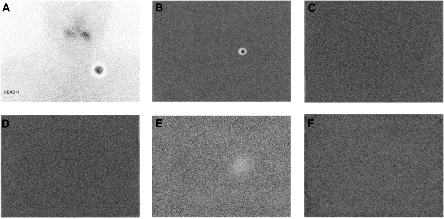
(A) Clinical 131I SPECT scan on which artifact was first encountered (high-count dark spot surrounded by broad light ring). (B) Scan with high-energy 131I source confirming existence of artifact. (C) From the morning of the patient scan, daily uniformity scan with low-energy 57Co source showing no artifact. (D) Scan with low-energy 99mTc source showing no artifact. (E) A few days later, scan with low-energy 99mTc source showing artifact at same position as in high-energy-source scan. (F) After application of optical coupling grease, scan with high-energy 131I source showing no artifact.
The quality control protocol of our hospital follows any instructions given by the manufacturers of our equipment. Thus, the quality of the Infinia Hawkeye system is evaluated daily, weekly, and quarterly (3). According to the manufacturer, the daily test should be a flood uniformity scan obtained with either a 14.8-MBq 99mTc point source or a 10-mCi (370-MBq) 57Co flood source. We use a 370-MBq 57Co flood source, collecting 4,000 kilocounts, before approving the system for any patient examinations each day. This test checks for any abnormality in the images and verifies the stability of the system. The daily uniformity image shown in Figure 1C was acquired the morning of the day on which our patient was scanned.
After the artifact started showing up with the high-energy source, we began a thorough investigation. First, peaking (10%) and tuning were done using a 99mTc point source to make sure that the window setting and photomultiplier tube voltage gain were within acceptable limits. An intrinsic flood image was acquired by altering the isotope—using a 14.8-MBq 99mTc point source placed at 5 UFOVs, collecting 3 million counts. The image was of uniform intensity and showed no artifact (Fig. 1D). However, after a few days, images obtained with the same low-energy source showed a light ring in the same location as on images obtained with the high-energy source (Fig. 1E). When a corrected matrix was applied, the images had one large, ring-type artifact, but images on an uncorrected matrix had a couple of additional spots that were similar to the ring-type artifact but smaller and of lesser magnitude. At that time, the artifact started appearing on images obtained with both low-energy and high-energy sources. We opened the detector head and found that the optical coupling grease between the crystal and the photomultiplier tube had melted and dispersed outward. Fresh optical coupling grease was applied, and subsequent images showed no artifacts (Fig. 1F).
DISCUSSION
Imaging artifacts can be classified as scanner-specific, patient-based, or physics-based (4). Photomultiplier tubes are the most sensitive part of a scintillation camera and can produce severe artifacts if not properly calibrated. Performance may deteriorate if the operator incorrectly or suboptimally handles the system (5). Ring artifacts may appear for several reasons. Faulty photomultiplier tubes or low or high voltage gain may result in cold or hot rings or an inner and outer halo of lower and higher counts. Maladjustment of the preamplifier and amplifier or a defect in the circuit of the photomultiplier tube can cause ring-type artifacts. In our case, it seemed as if the counts collected by the photomultiplier tube had shrunk to a smaller region, leaving the outer region void of counts. The cause of this problem was found to be leakage of the optical coupling grease. The severity of the artifact correlated with the amount of optical coupling grease dispersed, as evidenced by the corresponding figures. Initially, images taken with a low-energy source were uniform with the exception of a large light spot at the same location as on the ensuing images acquired with high-energy sources. For the images that had shown additional smaller spots on an uncorrected matrix, the optical coupling grease had dispersed to a lesser extent. Dispersion may be due to an increase in the temperature around the photomultiplier tubes. To avoid any thermal stress on the sensitive components of the γ-camera, the temperature gradient should not exceed 5°C per hour.
CONCLUSION
A SPECT artifact consisting of dark and light concentric rings was seen on a clinical scan obtained with a high-energy radioactive source. The artifact did not appear in daily uniformity testing using low-energy sources (a 14.8-MBq 99mTc point source or a 370-MBq 57Co flood source). However, it later began appearing consistently in all images regardless of whether a low- or high-energy source was used. The cause of the artifact was found to be gradual leakage of optical coupling grease, possibly because of an increase in local temperature. Fresh optical coupling grease was applied, and the artifact did not appear on later uniformity or patient images.
DISCLOSURE
No potential conflict of interest relevant to this article was reported.
Footnotes
Published online Apr. 13, 2017.
- Received for publication December 30, 2016.
- Accepted for publication March 27, 2017.


