


Article Figures & Data
Figures
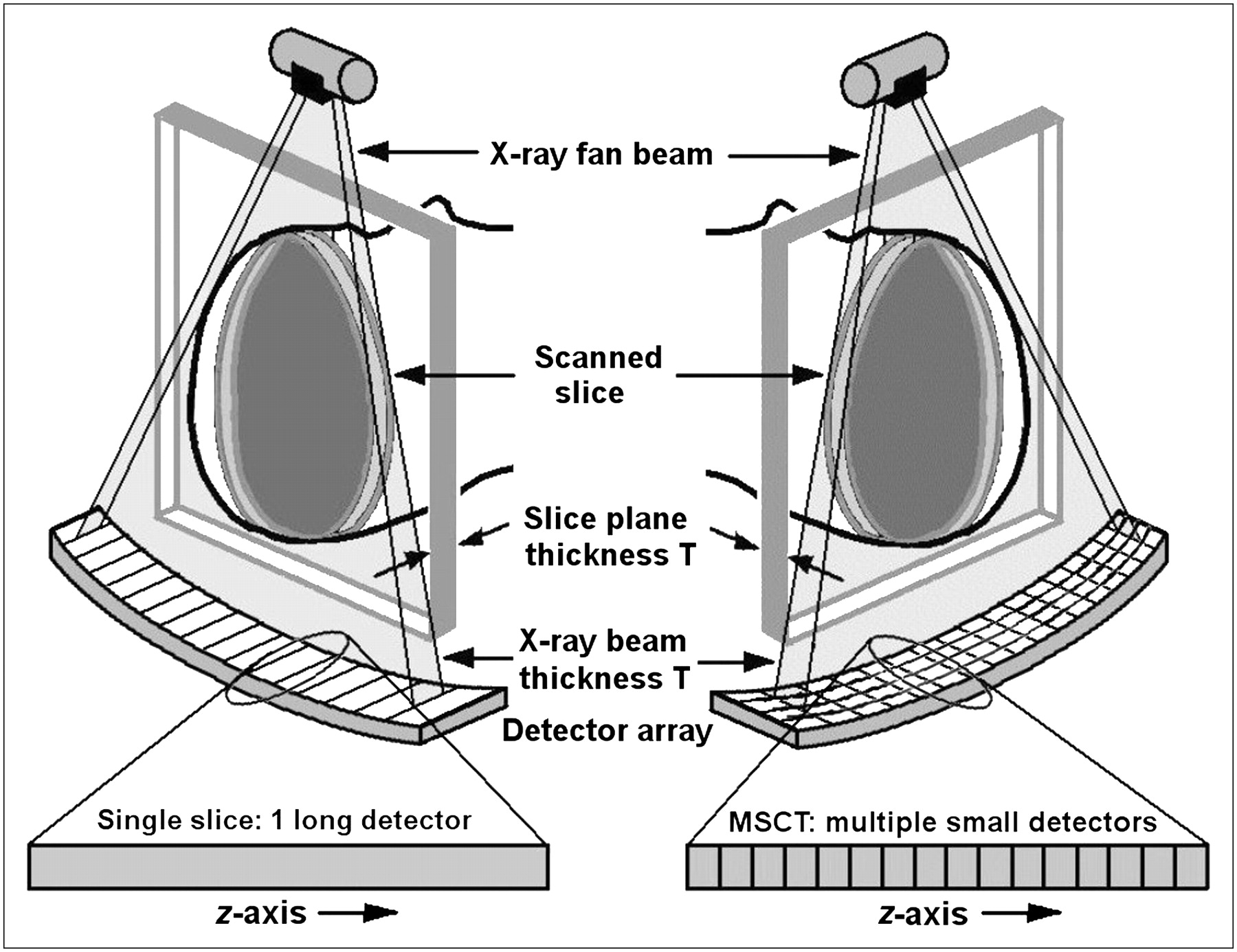
- FIGURE 1.
(Left) SSCT arrays containing single, long elements along z-axis. (Right) MSCT arrays with several rows of small detector elements.
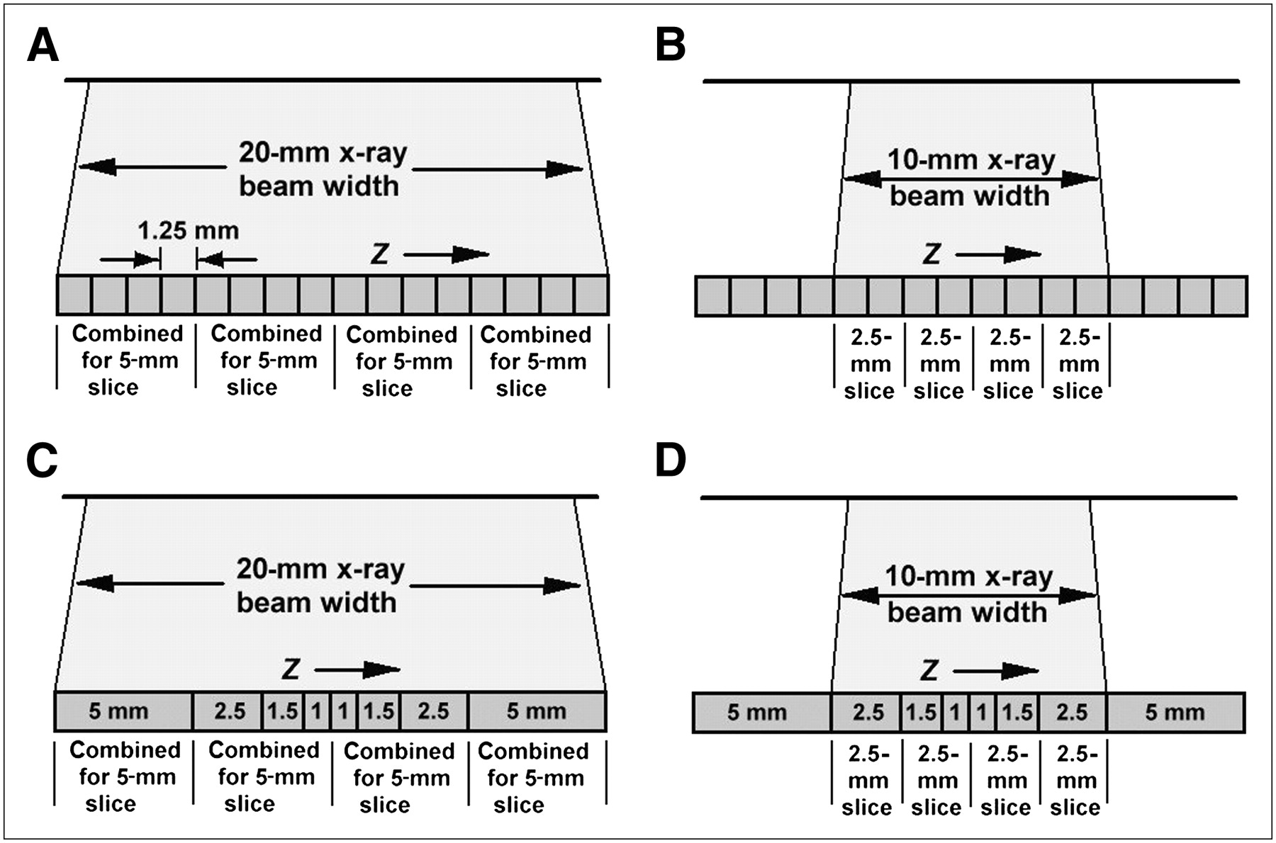
- FIGURE 2.
Flexible use of detectors in 4-slice MSCT scanners. (A) Groups of four 1.25-mm-wide elements are linked to act as 5-mm-wide detectors. (B) Inner 8 elements are linked in pairs to act as 2.5-mm detectors. (C) Inner, adaptive-array elements are linked to act as 5-mm detectors (1 + 1.5 + 2.5) and, together with outer, 5-mm elements, yield four 5-mm slices. (D) The 4 innermost elements are linked in pairs to form 2.5-mm detectors (1 + 1.5), which along with the two 2.5-mm detectors, collect data for four 2.5-mm slices.
- FIGURE 3.
Diagrams of various 16-slice detector designs (in z-direction). Innermost elements can be used to collect 16 thin slices or linked in pairs to collect thicker slices.
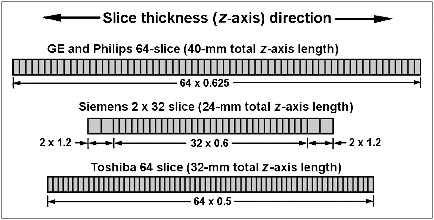
- FIGURE 4.
Diagrams of various 64-slice detector designs (in z-direction). Most designs lengthen arrays and provide all submillimeter elements. Siemens scanner uses 32 elements and dynamic-focus x-ray tube to yield 2 measurements per detector.
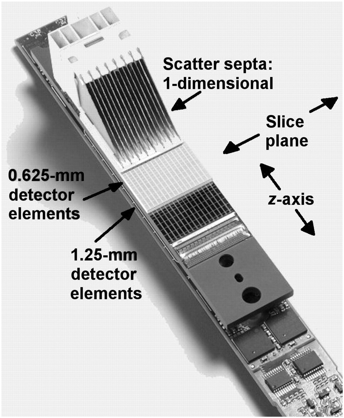
- FIGURE 5.
Section of 16-slice detector with scatter removal septa. Septa are sufficiently deep to eliminate nearly all scatter. Note smaller elements (0.625 mm, in this example) in center of array and larger (1.25-mm) outer elements. Also note dead spaces (lighter lines) between elements.
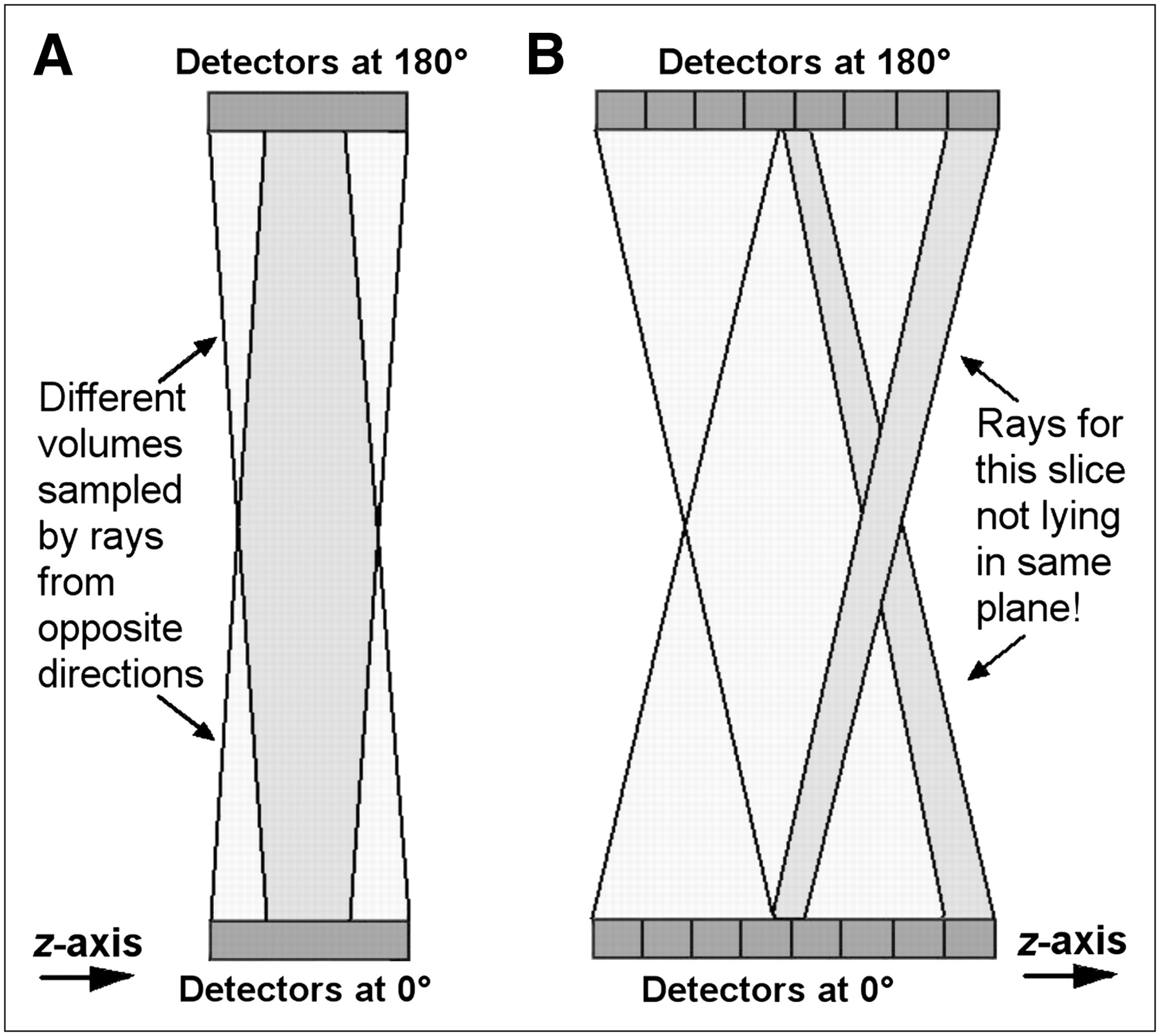
- FIGURE 6.
Cone beam effects in SSCT and MSCT. (A) In SSCT, divergent, cone-shaped x-ray beam irradiates different tissues—yielding different attenuation measurements—for parallel opposed rays, sometimes causing streaking for thicker slices. (B) Wider beams of MSCT accentuate cone beam shape and lead to rays that do not even lie within same plane. Cone beam reconstruction algorithms are generally required. opp. = opposite.
- FIGURE 7.
z-Spacing in helical CT. (A) Minimum z-spacing equal to d/2 (d = slice thickness) is achieved in SSCT with pitch of 1 and interpolation between interleaved parallel opposed rays. (B) With pitch of 1 in MSCT, parallel opposed rays overlap rather than interleave, giving z-spacing equal to d. (C) z-Spacing equivalent to that in SSCT is achieved with pitch that overlaps one slice thickness but results in double irradiation of some tissue. Reduced z-spacing can also be achieved with other pitches. det = detector; rot = rotation.
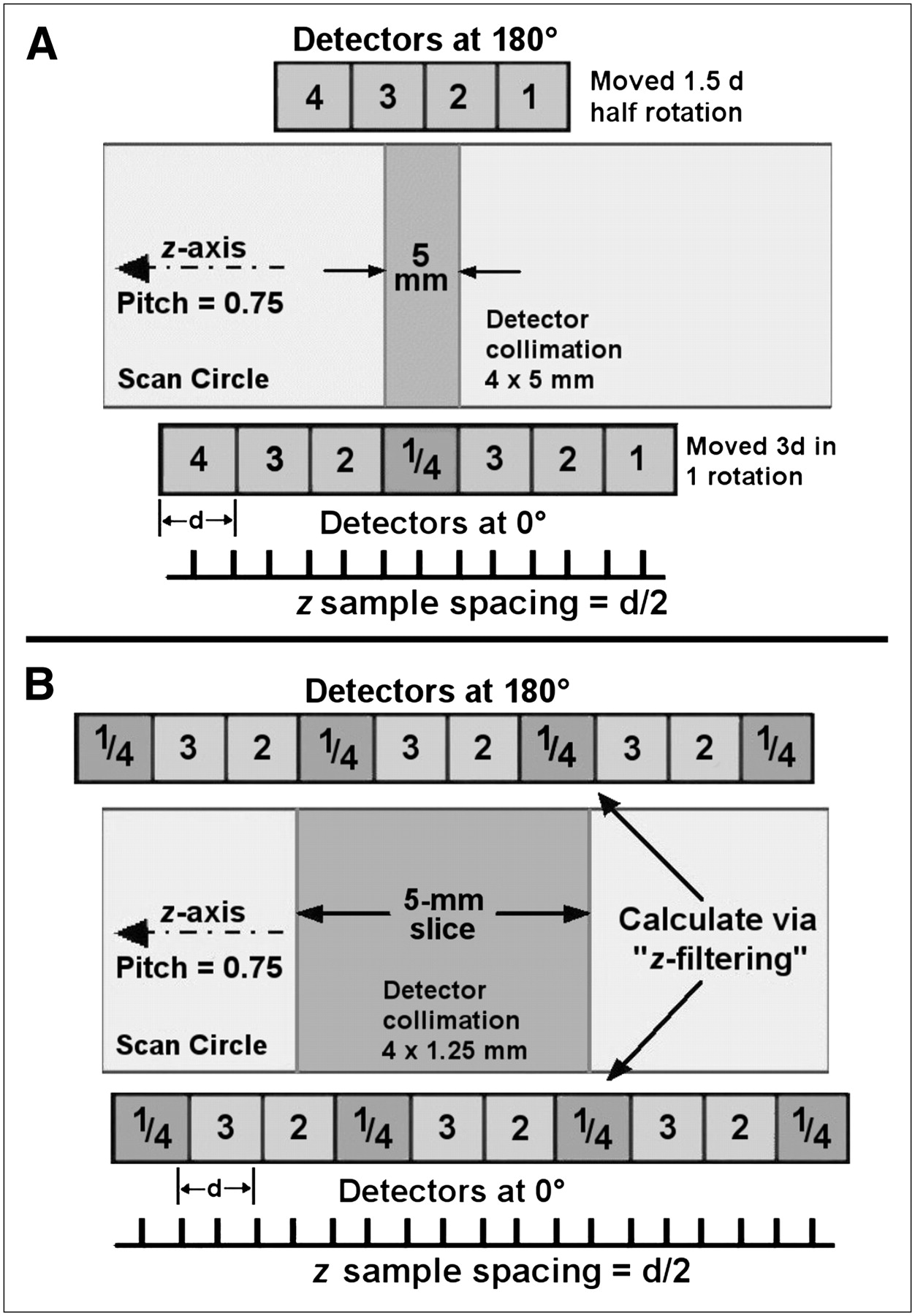
- FIGURE 8.
z Filtering. (A) For MSCT scans configured to acquire thicker slices (e.g., 5 mm), slices are interpolated as for SSCT. (B) For MSCT scans with small detector collimation, numerous measurements are obtained within slice plane (up to 13, in this example) to form thicker slices. Combining many measurements to form thicker slices is referred to as z filtering.
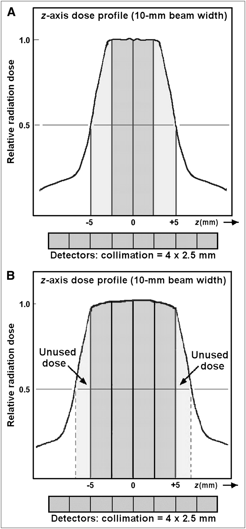
- FIGURE 9.
Geometric dose efficiency. (A) If MSCT detectors configured to acquire four 2.5-mm slices are irradiated with 10-mm-wide x-ray beam, as specified for SSCT, outer 2 slices will receive lower intensity and yield higher image noise. (B) To compensate, MSCT beams are widened to use only inner, nonpenumbra regions. Penumbra regions that were partially used in SSCT are discarded in MSCT, leading to reduced dose efficiency.
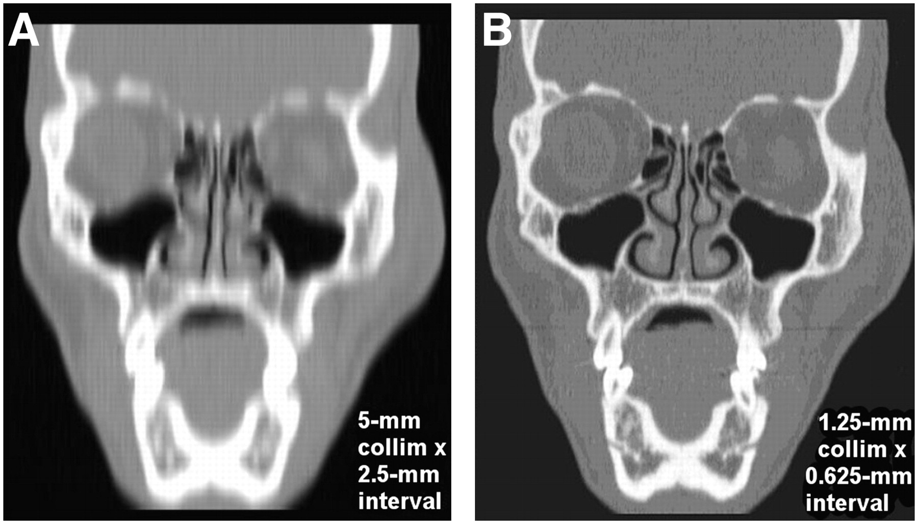
- FIGURE 10.
Coronal images formed from off-axis reformatting. (A) Thicker slices collected by SSCT lead to poor-quality, less efficacious off-axis images. (B) Thinner slices collected by MSCT lead to high-quality reformatted images, often with resolution equivalent to that within slice plane. collim = collimation.


Tables
Total beam collimation (mm) Detector configuration CTDIw relative to 10-mm beam 5 4 × 1.25 mm 1.22 10 4 × 2.5 mm 1.00 15 4 × 3.75 mm 0.93 20 16 × 1.25 mm 0.89 40 16 × 2.5 mm 0.83 Because discarded penumbra represents smaller fraction of total beam width, CTDI values decrease with increasing beam widths (combined data from GE Healthcare 4-slice and 64-slice MSCT scanners).


Jump to section
Related Articles
Cited By...
- Sensitivity of modern multislice CT for subarachnoid haemorrhage at incremental timepoints after headache onset: a 10-year analysis
- Identifying the Functional Macropore Network Related to Preferential Flow in Structured Soils
- Adult patient radiation doses from non-cardiac CT examinations: a review of published results
- Assessment of Patient Exposure to X-Radiation from SPECT/CT Scanners
- Radiation dose and cancer risk in retrospectively and prospectively ECG-gated coronary angiography using 64-slice multidetector CT