

FIGURE 4.

FIGURE 4.
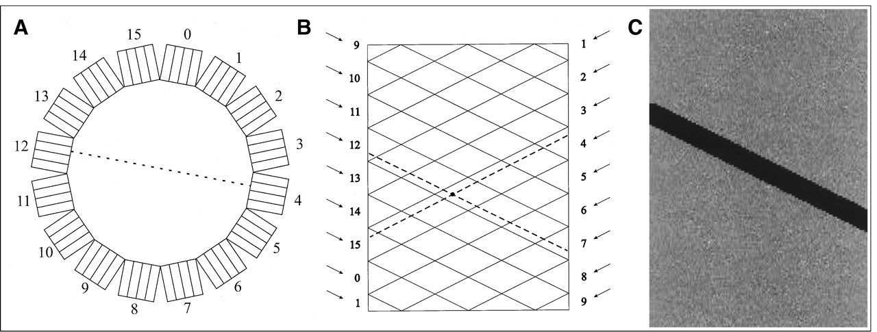
Sinograms and ring gantry. (A) Ring gantry is shown with 16 detector blocks. (B) In sinogram, events involving Block 12 are displayed along diagonal as shown. All blocks in coincidence with Block 12 (Blocks 1−7) are also displayed along diagonals, but slanting in opposite direction. LOR shown in (A) as dashed line is represented in sinogram in (B) as intersection of dashed lines from Block 12 and Block 4, respectively. (C) If particular block in scanner is malfunctioning, it will lead to diagonal streak in sinogram as shown here. This fact is used in routine PET quality control to determine which blocks may need to be serviced.


