


Abstract
The goal of this article is to make the PET/CT and SPECT/CT operator aware of common artifacts found in CT. In diagnostic imaging, the ability to render an accurate diagnosis requires the technologist to take steps to optimize image quality and recognize when image quality has been compromised—that is, when there is an image artifact. One way these artifacts occur is through the inability of the CT linear attenuation image to precisely represent the linear attenuation map of a 2-dimensional section through the body. The reasons for this inability are multifold. First, CT is subject to the laws of x-ray quantum physics resulting in noise in all CT images. Moreover, all current CT x-ray systems generate a spectrum of energies. Also, CT scanners use detectors of finite dimension, as are the x-ray focal spots; reconstruct images from a finite number of samples distributed over a finite number of views; and acquire the data for each reconstruction over a finite period.
Although the appearance and cause of CT artifacts might be understood by the CT technologist (1,2), the proliferation of hybrid SPECT/CT and PET/CT systems may find nuclear technologists disadvantaged. Publications featuring hybrid systems generally focus on CT as an attenuation correction tool (3,4) and provide little information on the optimization of CT image quality through artifact recognition. What follows is a description of common CT artifacts and their root causes.
STREAK ARTIFACTS
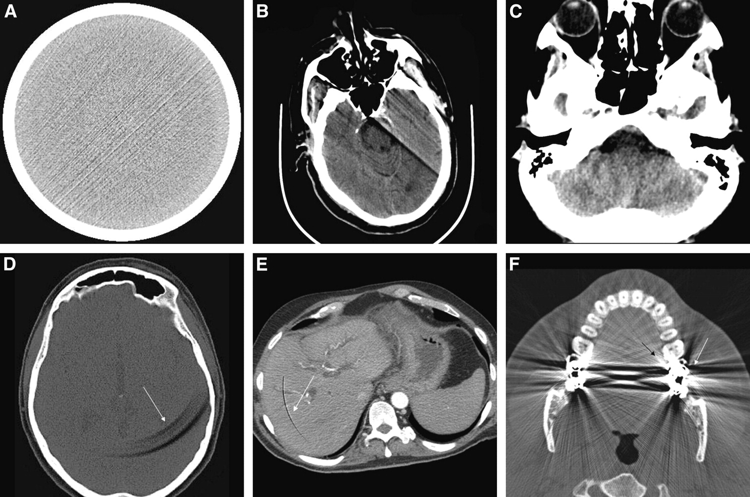
Streak artifacts may be produced when the object of interest is moved, undersampled, or corrupted because of data sampling errors. CT assumes that the object being imaged is static (unchanging) during the scan and that the object is imaged with adequate sampling (rays and views) and without inconsistency (photon or counting interruptions). Figure 1A shows streak artifacts in a uniform phantom. Undersampling may result in the presence of streak artifacts that generally emanate from objects of high density and sharp edges.

Examples of CT artifacts: streak artifact (A), motion artifact (B), beam-hardening artifact (C), ring artifacts (D and E), and bloom artifact (F).
MOTION ARTIFACTS
Motion artifacts appear as object boundaries that are ill-defined and associated with streaking adjacent to structures with high densities such as contrast-filled vessels. Motion artifacts commonly result in shape distortion and bright or dark shadowing, which can appear like disease. Sources of motion-related artifacts (5,6) fall into the categories of voluntary motion and involuntary motion. Voluntary motion is often associated with respiration, external body movement, and swallowing. Involuntary movement is attributed to the beating heart, peristalsis, coughing, and sneezing. All sources of motion result in movement of the object relative to the scanning plane.
The technologist must be keenly aware of the patient's condition and inherent motion associated with imaging the anatomy of interest. Figure 1B shows an example of a streak artifact caused by motion as a result of swallowing during the scan. Although manufacturers have implemented routine protocols to balance trade-offs in image quality and patient compliance, as well as sophisticated methods (prospective electrocardiography triggering and pulmonary gating) to image organ systems in motion, the technologist should consider adjustments to rotation speed and pitch to optimize study duration and maximize patient compliance.
BEAM-HARDENING ARTIFACTS
Beam-hardening artifacts result from the nonlinear (polychromatic) nature of the x-ray beam as it leaves the x-ray tube housing and from limitations associated with preferentially eliminating lower-energy photons from the beam—thus hardening the beam. Recognizing that the x-ray beam is polychromatic and that attenuation coefficients are energy-based, manufacturers have attempted to decrease beam-hardening effects through the use of inherent and protocol-selected beam filtration, software corrections, and calibrations specific to each peak kilovoltage setting. Beam hardening is a complex paradigm that involves trade-offs related to patient dose, image noise, contrast, and CT number uniformity. Therefore, technologists must carefully consider selection of imaging parameters, filters, and patient position within the scanner.
Beam hardening presents as dark banding between dense objects such as bone. Variations of contrast and intensity across an object can appear like certain pathologic conditions and potentially affect diagnosis. The radiologist can identify beam-hardening artifacts by interrogating multiple planes, because the dark banding generally aligns with the object path. Figure 1C shows an example of beam hardening.
RING ARTIFACTS
Ring or band artifacts are caused by a variety of factors influencing the counting accuracy of a detector, such as gain variations, radiation damage to the detector, and linearity irregularities. Ring and band artifacts appear as intensely bright or dark circular artifacts within the image and, when subtle, can mimic certain pathologic conditions. When pronounced, these artifacts are unlikely to cause misdiagnosis but will generally render the scan unreadable. Figures 1D and 1E demonstrate partial rings.
It is important to follow routine system calibration schedules aimed at establishing the proportionality of detector response for different scanning conditions (kilovoltage, collimator aperture, etc.) in an effort to minimize the aforementioned effects. It is also important to maintain the specified ambient room conditions for the scanning room to minimize temperature drift over time.
BLOOM ARTIFACTS
Bloom artifacts are a result of partial-volume effects or underranging caused by areas of photon starvation propagated by high-density structures, such as metal, within the scanned object. When subtle, these artifacts appear as shading, and when severe, as high-intensity streaks and areas of photon starvation. Figure 1F shows partial-volume artifacts. They are generally easily identified because they emanate from attenuation at sites of orthopedic implants, surgical staples and clips, and calcium deposits.
Manufacturers attempt to mitigate these artifacts through the use of interpolation models and reconstruction algorithms. For the technologist, decreasing pitch and applying z-axis filtering can be helpful.
CONCLUSION
Although CT artifact recognition has been well documented for the CT technologist, technologists with a nuclear medicine background responsible for SPECT/CT and PET/CT hybrid imaging systems may be less familiar with these artifacts. This article has attempted to make technologists aware of common artifacts found in CT and is not intend to be an exhaustive or authoritative source.
Footnotes
-
COPYRIGHT © 2008 by the Society of Nuclear Medicine, Inc.
References
- Received for publication September 19, 2007.
- Accepted for publication March 4, 2008.


