


Article Figures & Data
Figures
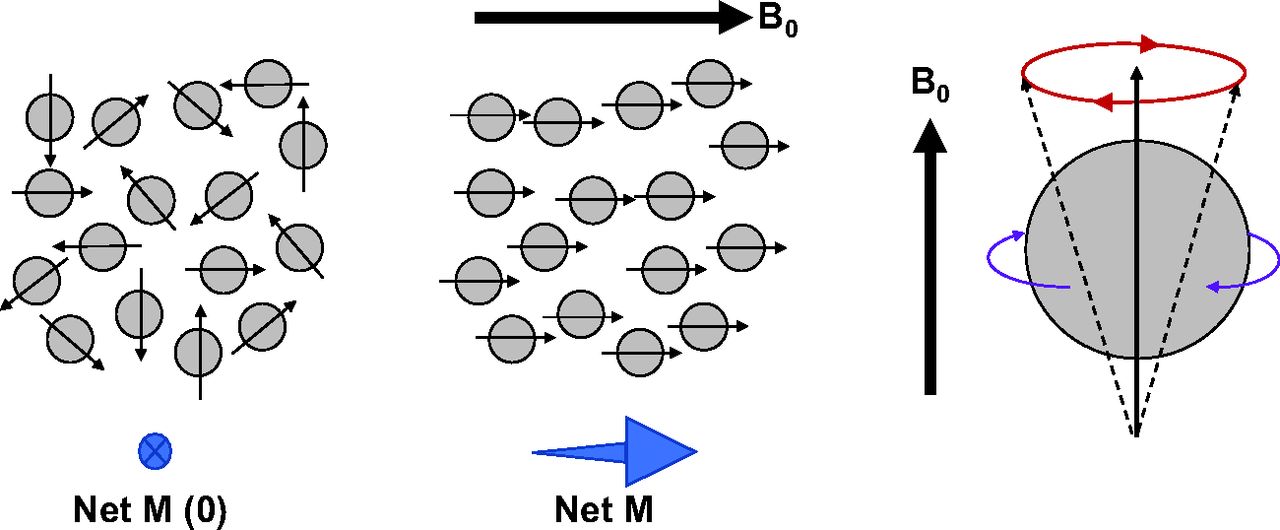
- FIGURE 1.
Nucleus spin creates polarity with random distribution, producing net magnetic vector (M) of zero (left). Application of strong magnetic field (B0) creates alignment of proton dipoles, producing net M aligned with B0 (middle). Although proton dipoles spin on their axis (purple arrows) to produce small magnets, movement in presence of magnetic field is gyromagnetic (red arrows) and termed precession (right).
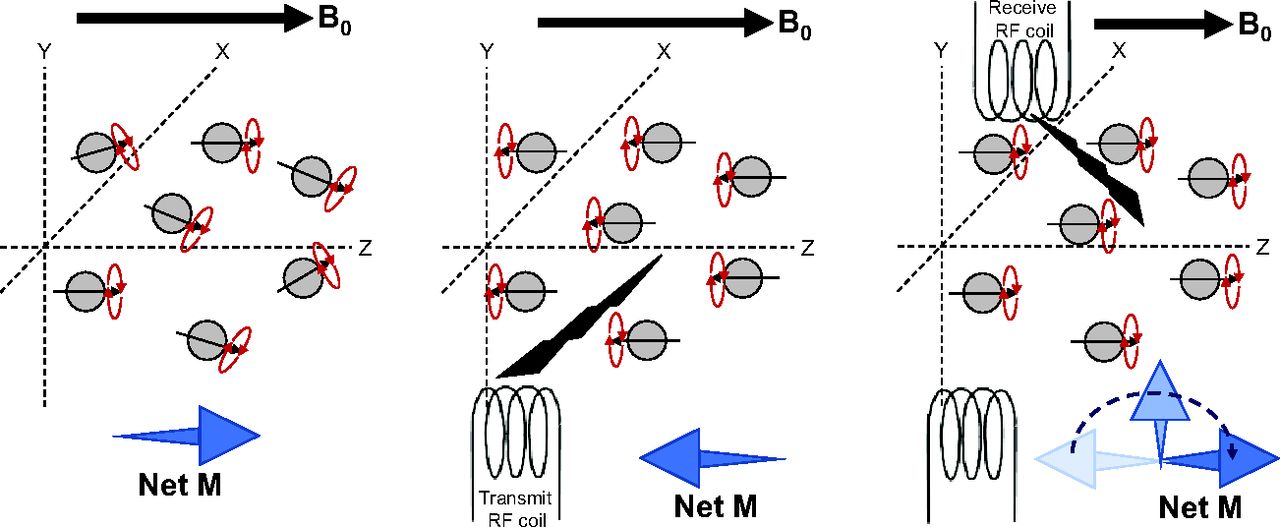
- FIGURE 2.
Nucleus spin creates polarity with magnetic field (B0) and positive alignment of proton dipoles with z-axis, producing net magnetic vector (M) and random precession (left). Radiofrequency (RF) transmission causes aligned proton dipoles to flip to negative on z-axis and causes precession to come into phase (middle). Relaxation results in reversion of net M, producing FID signal at RF receiver coil (right).
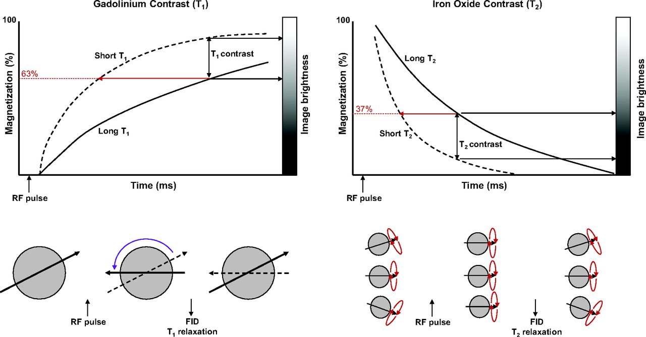
- FIGURE 3.
Schematic representation of principle of T1 and T2 contrast enhancement by altering relaxation times. T1 plot (top left) shows effect of shortening relaxation time with gadolinium contrast and resultant positive enhancement of contrast. Likewise, T2 plot (top right) shows effect of shortening relaxation time with iron oxide contrast and resultant negative enhancement of contrast. (Adapted with permission of (11).) RF = radiofrequency.
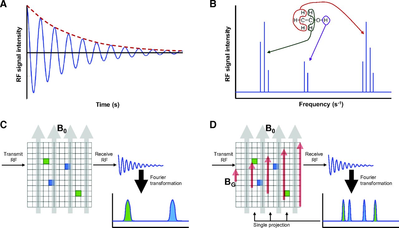
- FIGURE 4.
(A) FID with decreasing harmonic oscillation. (B) Fourier transformation of FID creates frequency-domain nuclear MR spectrum. For MRI, clusters represent different tissues, as is schematically represented here for nuclear MR spectroscopy, with each cluster representing a different molecular array of hydrogen (as depicted with red, green, and purple hydrogen atoms). (C) In static magnetic field (B0), nuclear MR spectrum identifies different tissues but not spatial location. (D) Application of gradient magnetic field (BG), depicted in red, allows spatial identification for that gradient projection. Rotating gradient magnetic field allows multiple projections to be collected and reconstructed. RF = radiofrequency.
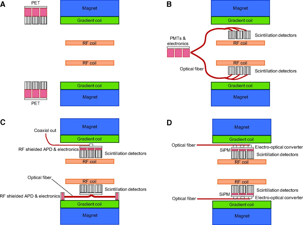
- FIGURE 5.
(A) Separate but linked PET/MR without option for simultaneous acquisition. (B) Integrated and simultaneous PET/MR housing radiofrequency (RF)-sensitive PMTs and electronics outside gantry. (C) Two versions of integrated PET/MR using RF-shielded APDs and electronics. Top half of schematic represents RF-shielded APD inside gantry, whereas bottom half uses optical fiber to connect to RF-shielded APDs at edge of MR field of view. (D) Integration of RF-compliant SiPM with optical fiber output obviates RF shielding of PET components.
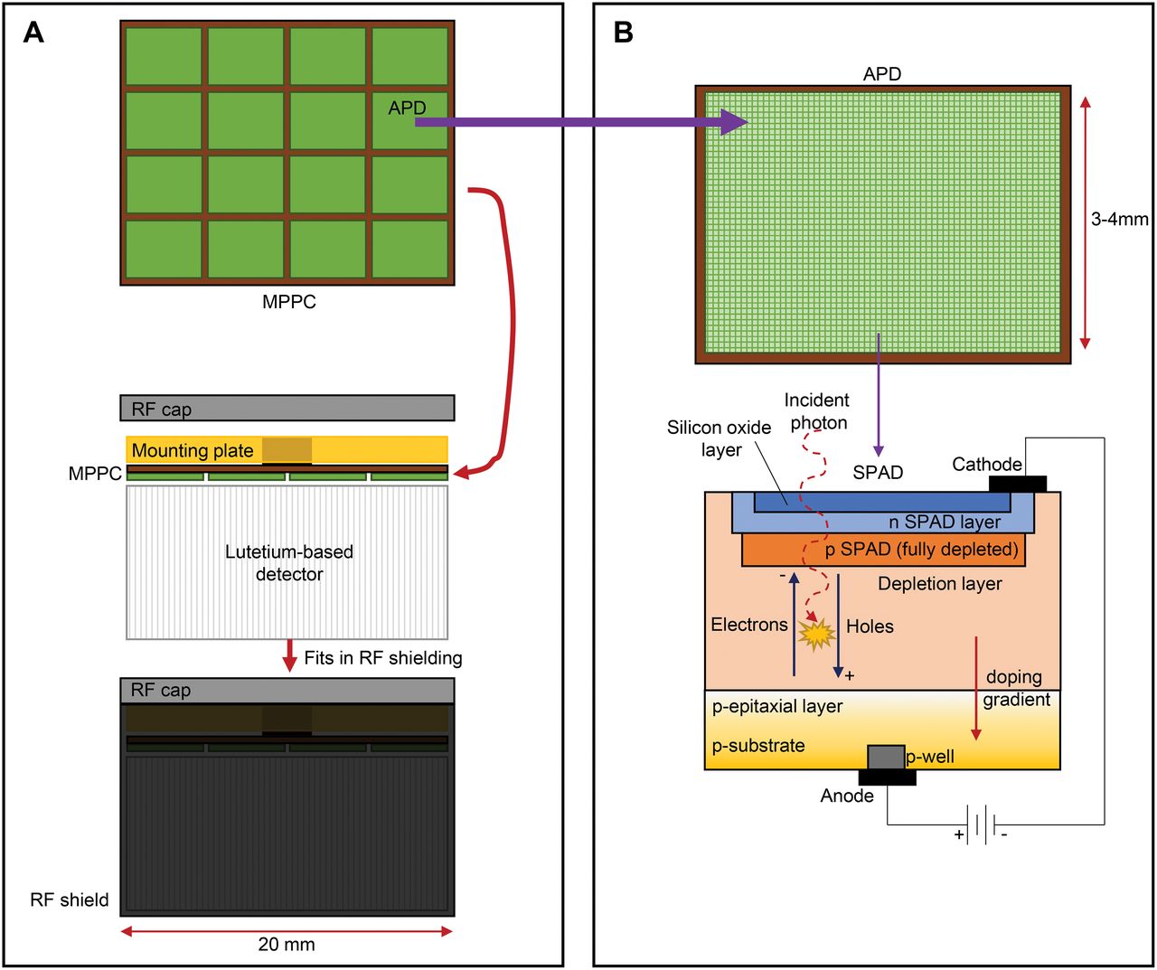
- FIGURE 6.
(A) Multipixel photon counter (MPPC) array comprises multiple APDs and is mounted to lutetium-based detector, which is housed in lightproof radiofrequency (RF) shield. These small individual MPPC units (2 cm) make up PET detector system. (B) APD (in this case, Geiger-mode APD) comprises pixels (single-photon avalanche diode, or SPAD). Layers of SPAD use silicon dioxide layer through which incident photons interact in depletion layer. Excitation causes electron holes that migrate to positive and negative doped layers to produce signal.
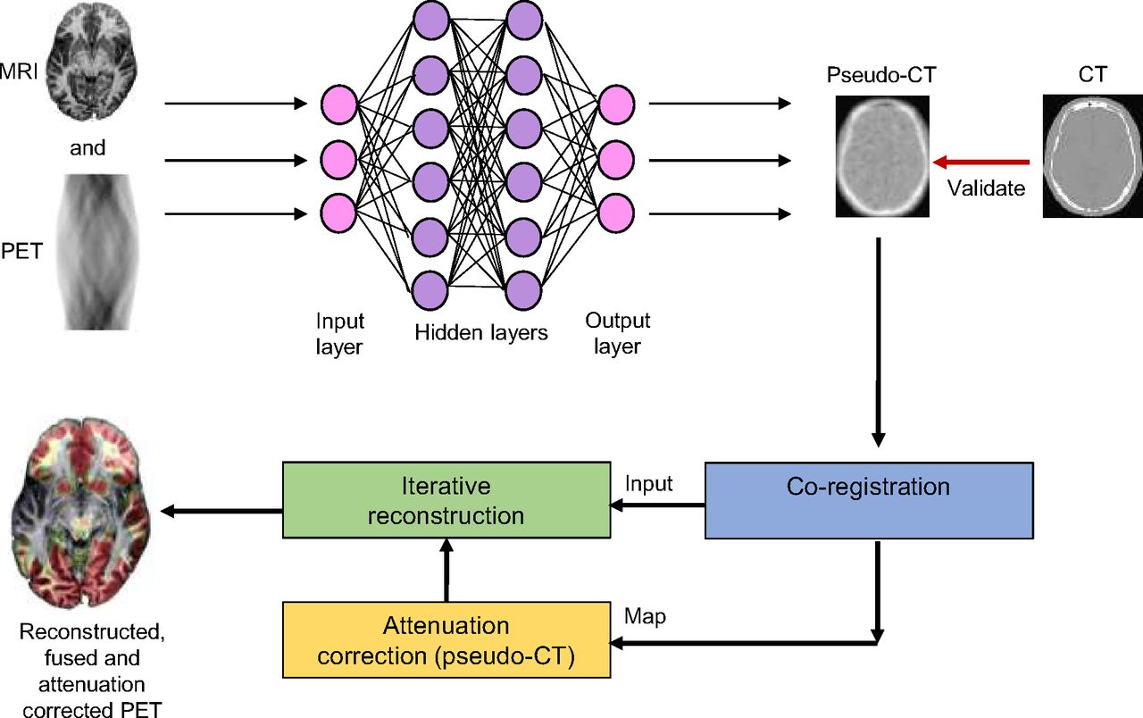
- FIGURE 7.
Model for potentially using CNN for improved pseudo-CT attenuation correction in PET/MRI. (Adapted from (16).)


In this issue


Jump to section
Related Articles
Cited By...
- PET-MRI for evaluation of response to radiochemotherapy in patients with locally advanced cervical cancer
- PET-MRI for evaluation of response to radiochemotherapy in patients with locally advanced cervical cancer
- PET/MRI, Part 4: Clinical Applications
- PET/MRI, Part 3: Protocols and Procedures
- Once Again--The SNMMI "Nailed It"!