


Article Figures & Data
Figures
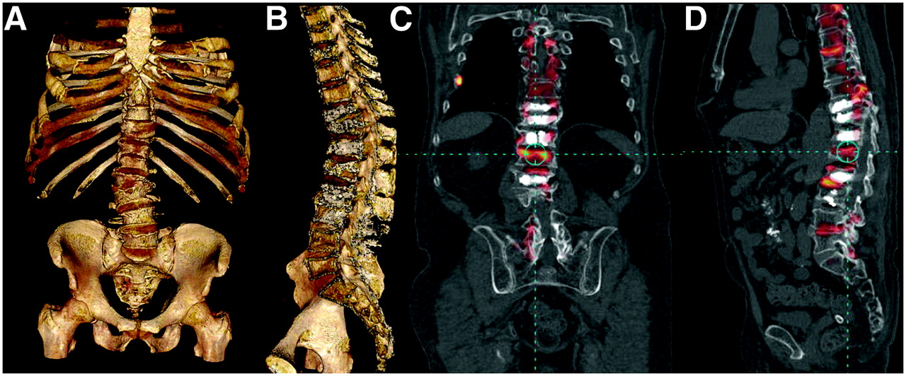
- FIGURE 1.
3D 18F-FDG PET/CT fused image showing rib and vertebral metastases. Electronic pain control module and electrodes are present.
- FIGURE 2.
18F bone scan MIP images without and with attenuation correction for small and very large patients. (A and B) Emission-only and attenuation-corrected anterior view of small-framed patient. (C and D) Emission-only and attenuation-corrected anterior view of obese patient. Attenuation correction is vital for detection of small lesions and provides excellent imaging of very large patients. PET is more sensitive than single-photon imaging to attenuation effects.
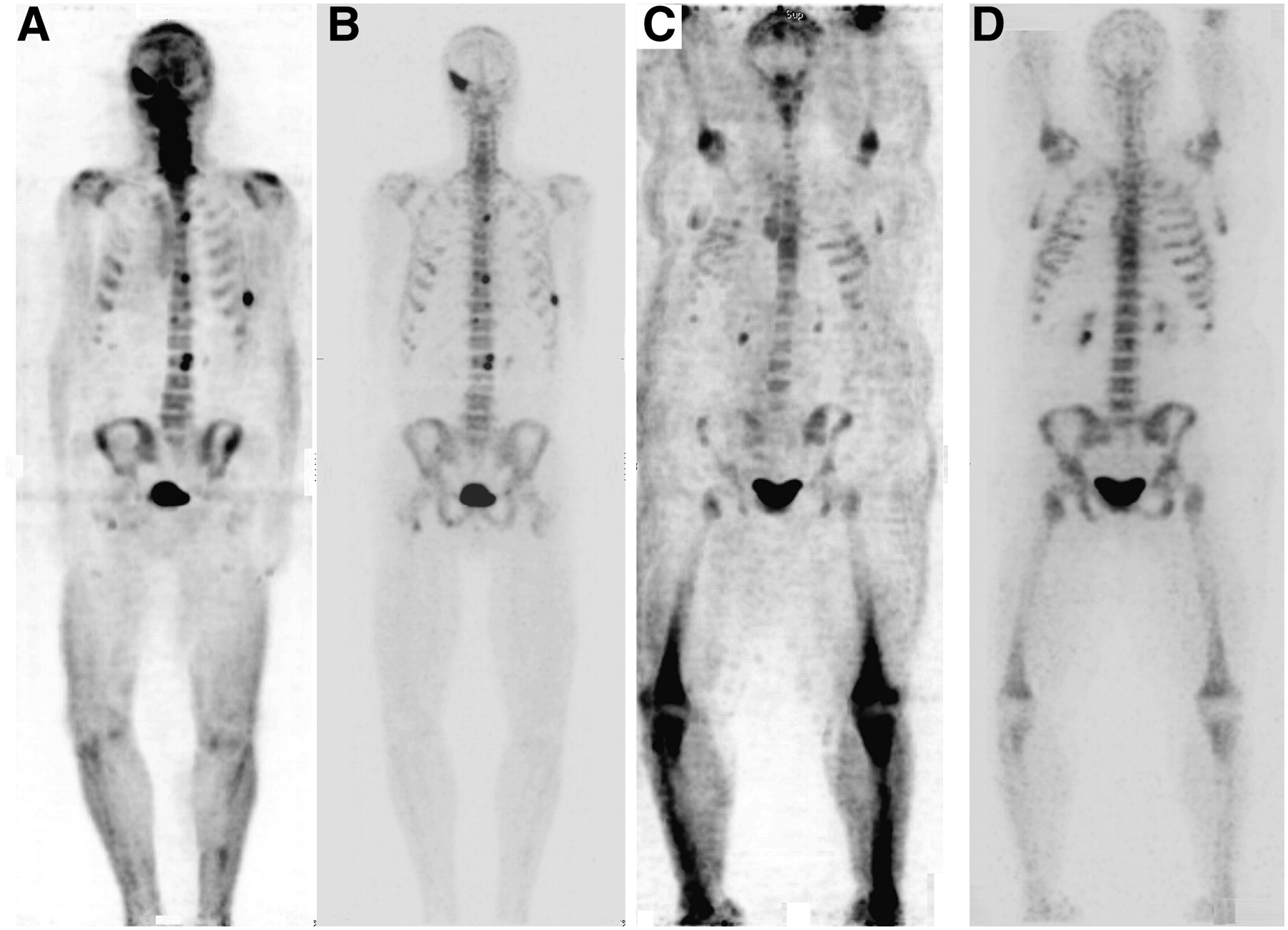
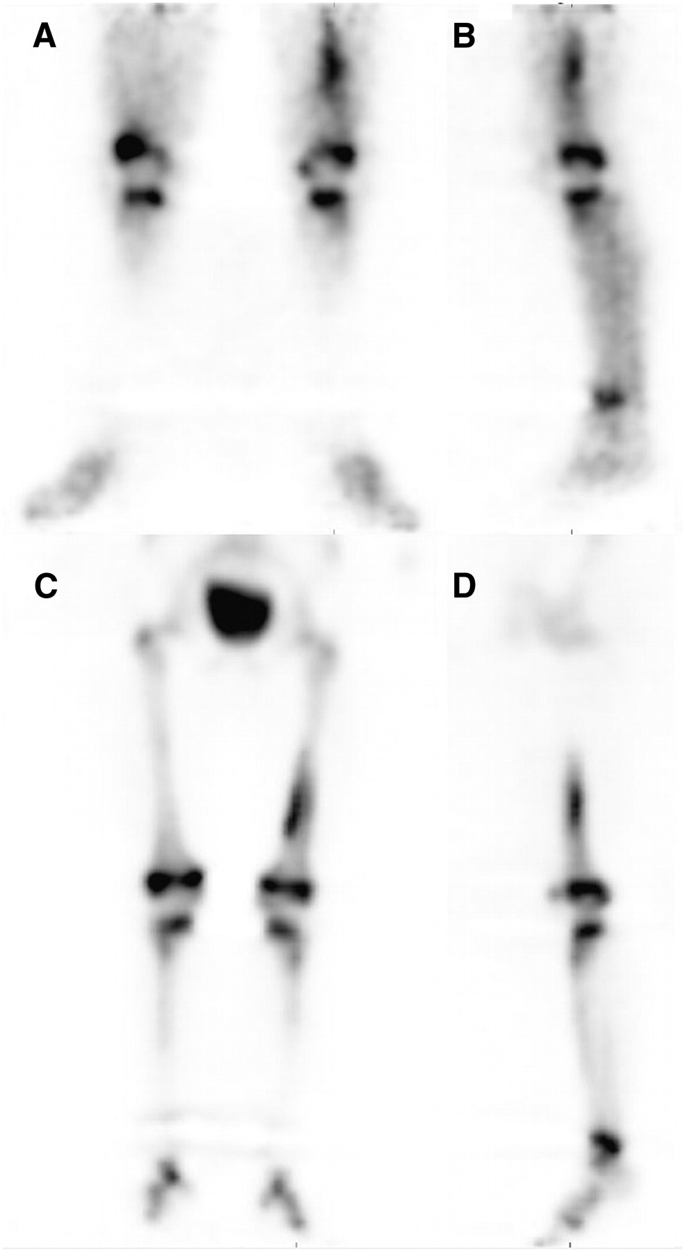
- FIGURE 3.
Standard 99mTc-MDP planar bone scan and 18F bone scan of same patient obtained within a few days of each other (courtesy of Seattle Nuclear). (A and B) Anterior and posterior views showing increase in uptake in vertebra and left rib. (C and D) Anterior and posterior MIP views showing numerous additional metastases. Even in retrospect, few of the 18F lesions can be seen on planar images.
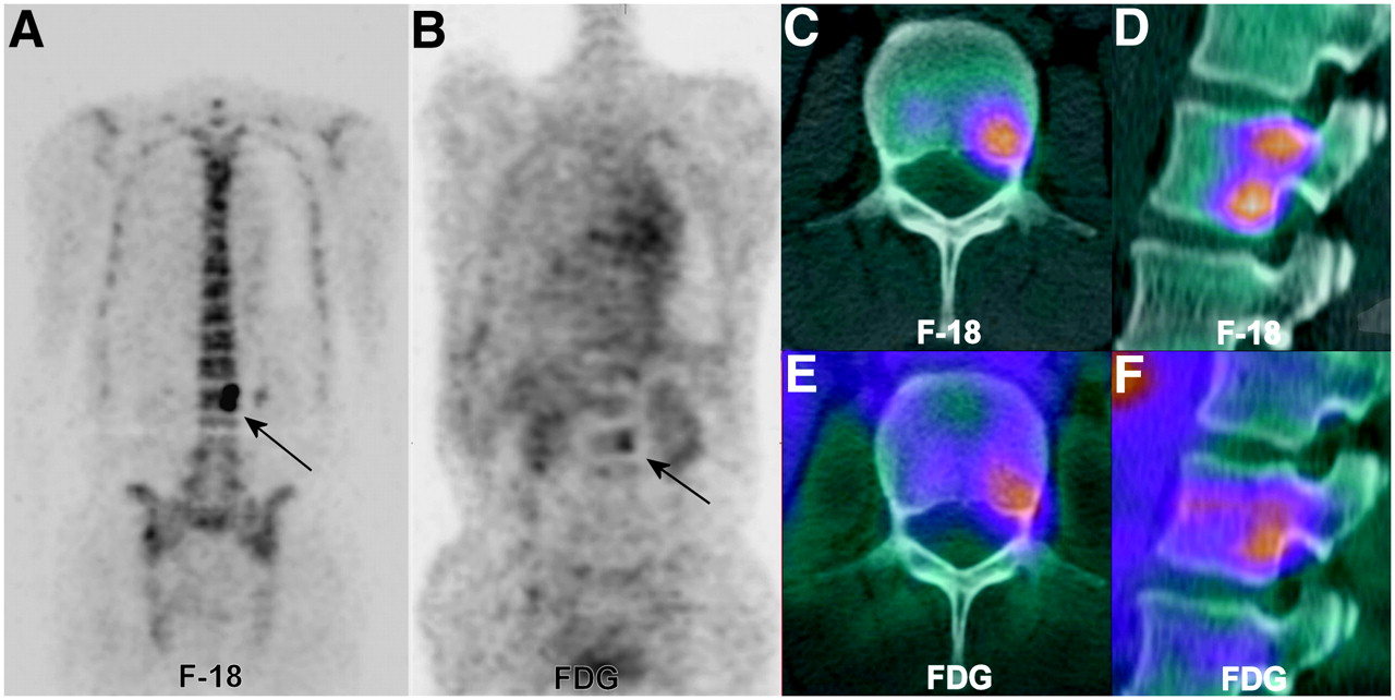
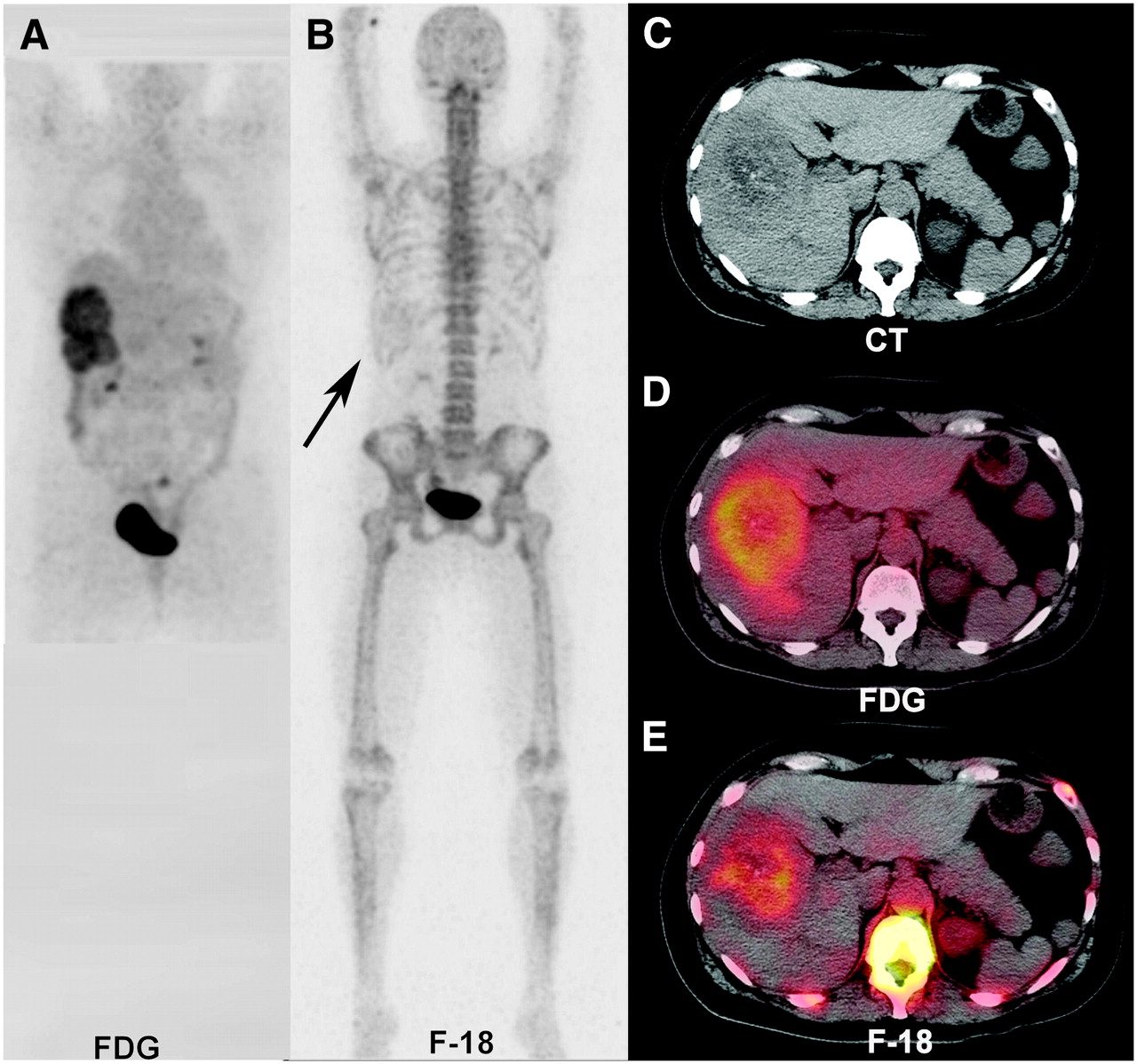
- FIGURE 4.
18F-FDG PET and companion 18F bone scan of metastatic disease of lumbar vertebrae. 18F bone scan, 18F-FDG PET scan, and CT study are from same patient taken separately in same week. (A) Coronal slice from 18F bone scan showing 2 distinct lesions in left portion of L2 vertebral body (arrow). (B) Identical slice from 18F-FDG PET scan faintly positive for more inferior area of L2 (arrow). (C and D) Transaxial and sagittal fused CT and 18F bone scans showing inferior lesion on transaxial slice and 2 lesions on reformatted sagittal slice through same area. (E and F) 18F-FDG PET fusion with same CT scan shows only inferior lesion in L2. Physiologic osteoblastic uptake in tumor may be severalfold greater with 18F than with 18F-FDG or 99mTc-MDP.
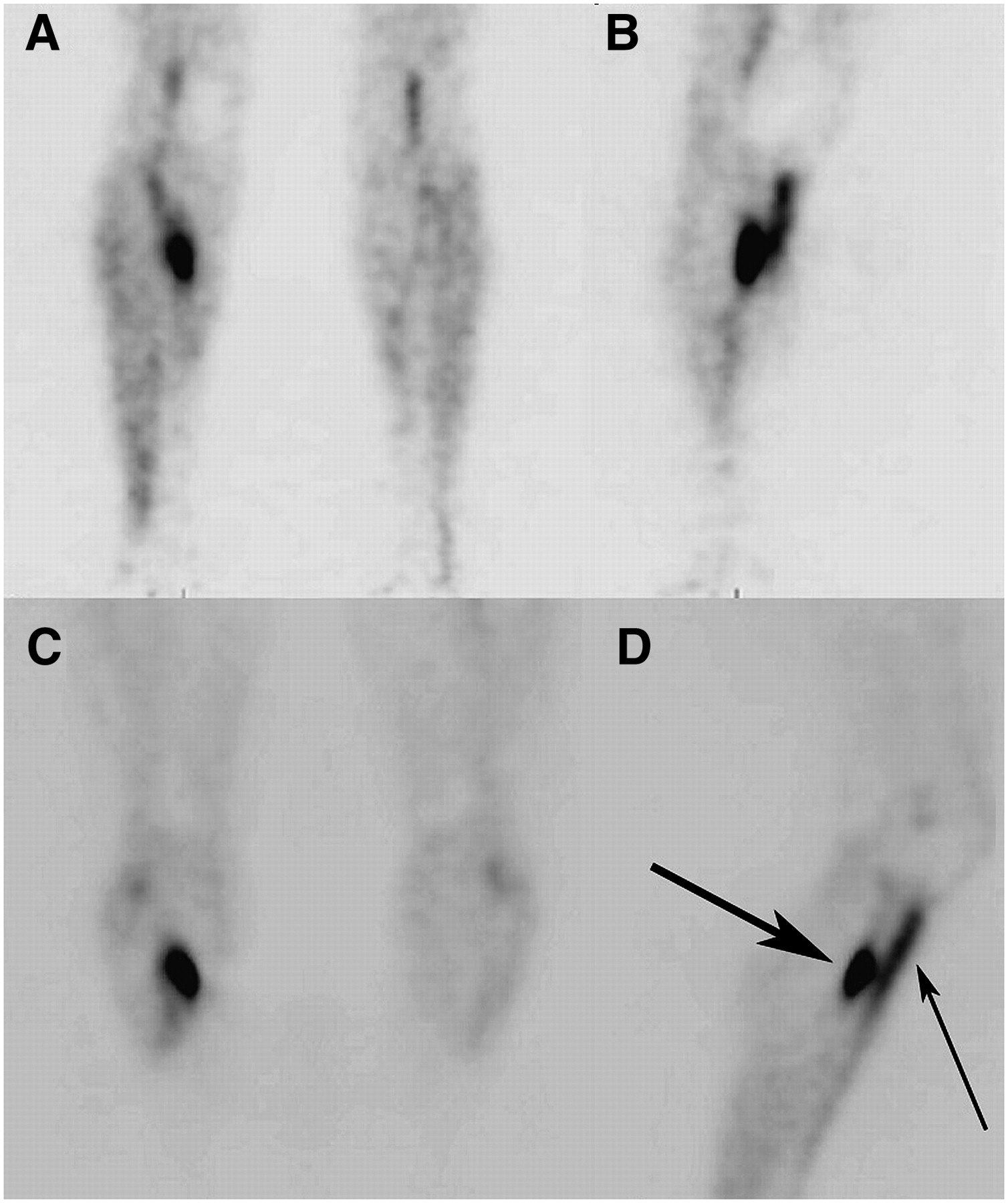
- FIGURE 5.
Dual-tracer acquisition: combined injection of 18F-FDG and 18F. (A) Two views of combined tracer showing soft-tissue, lytic bone, and osteoblastic bone lesions. Arrows point to small osteoblastic lesion in sacrum. (B and C) Fused CT and 18F-FDG/18F PET characterizing lesion (arrows) as small and osteoblastic in central body of S2. (D) CT image of B with fusion shows sclerotic nature of S2 lesion. Note sclerotic focus centrally within S2 body in lower left corner of CT image and same area on fused images. This area would probably not have been visualized on plain 18F-FDG scan.
- FIGURE 6.
18F-FDG and 18F scans of metastatic colon cancer fused to same “isoaligned” CT scan. (A) Large lesions dominating right lobe of liver. (B) Faint tracer uptake (arrow) in right upper quadrant in otherwise negative PET bone scan. (C) Transaxial CT slice of larger lesion showing calcifications in tumor. (D) Prospective fusion of 18F-FDG PET and CT showing peripheral hypermetabolic margin of tumor with decreased metabolism in center of mass. (E) Retrospective fusion of 18F-FDG PET and previous CT delineating extent of tumor calcifications and central necrosis.
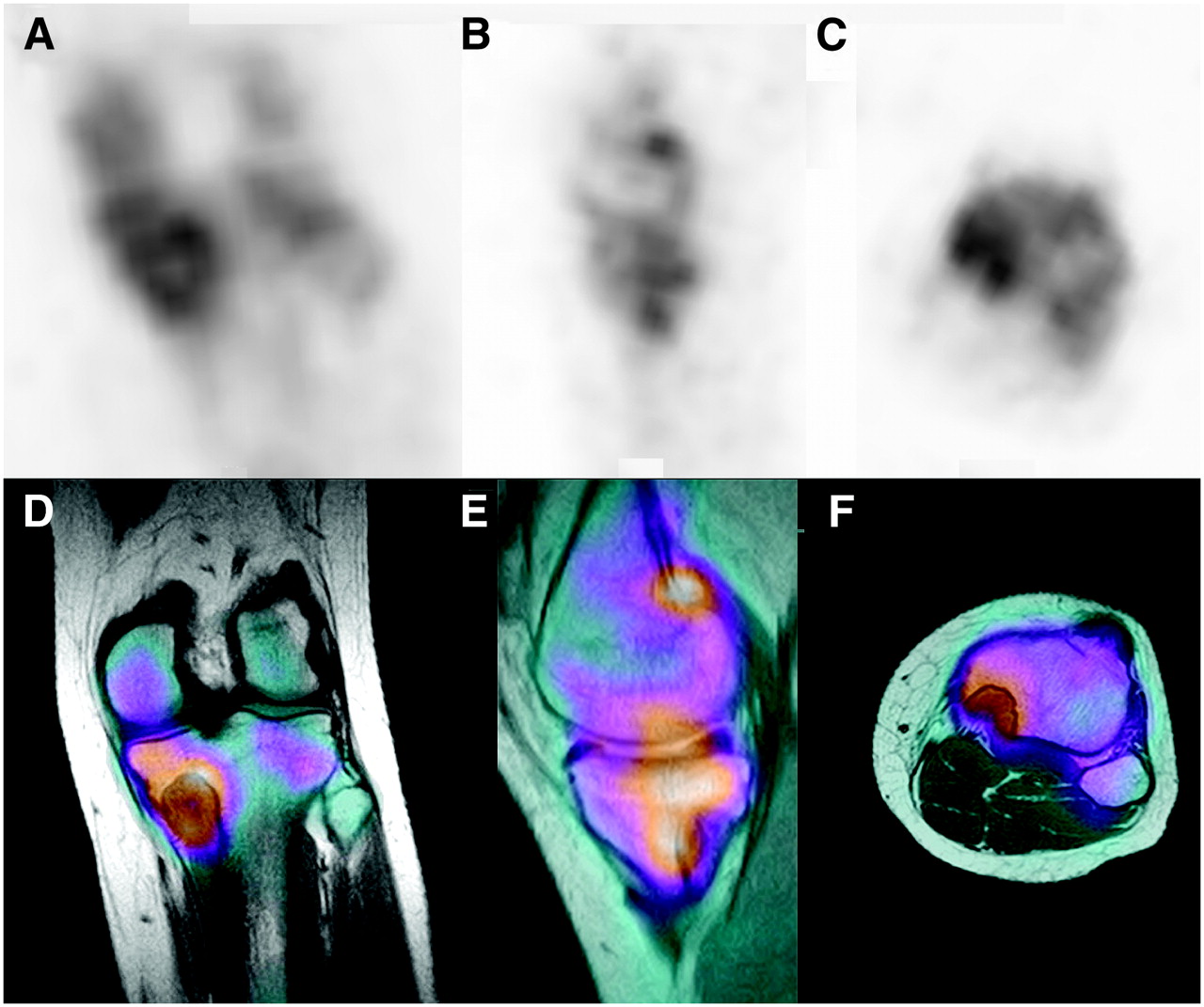
- FIGURE 7.
Medial tibial lesion in runner: positive 18F scan followed by MRI. (A–C) Coronal, sagittal, and axial images of main lesion and uptake in plateau, adjacent medial femoral condyle, and gastrocnemius origin. (D–F) Complementary images from fusion with MRI clarify extent and distribution of uptake. Principal uptake is due to weakened plateau from underlying benign tumor.
- FIGURE 8.
Stress fracture and shin splints of lower leg. (A and B) Blood-pool scan showing posterior stress fracture and anterior shin splints. (C and D) Delayed-image scan of stress fracture (large arrow) and shin splints (small arrow).
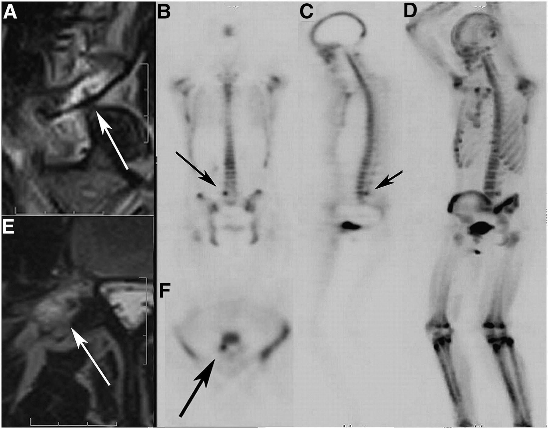
- FIGURE 9.
Incipient fracture of right L5 pedicle/pars interarticularis area in young athlete. (A and E) Sagittal and transaxial T2-weighted MR images of incipient pars fracture. Arrows point to incomplete linear defect within, surrounded by edema. (B, C, and F) Bone scan localizing and confirming lesion in right L5 pars interarticularis area (arrows). (D) MIP of emission-only scan of patient. Note sharply defined lesion not obscured by bone edema.
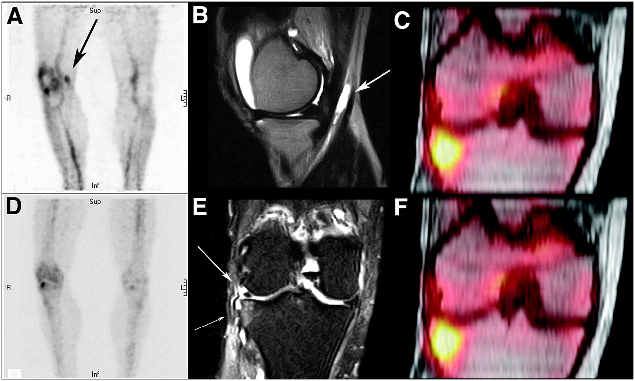
- FIGURE 10.
Lateral knee pain with previous lateral meniscectomy. (A) Blood-pool scan showing hyperemia of synovial lining (pes anserine bursitis) and bony lateral tibial plateau. Arrow points to bursitis. (B) Large joint effusion and anserine bursitis (arrow) in same medial area of knee as in A. (D) Delayed image showing only single remaining hot area for lateral plateau. (E) Coronal short-τ inversion recovery MR image showing intact meniscal remnant (large arrow) and lateral tibial plateau signal abnormality (small arrow). (C and F) Fused 18F scan and MR image of knee localizing and confirming lateral plateau injury.
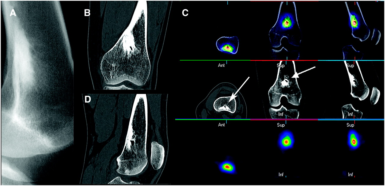
- FIGURE 11.
Deep knee pain in young woman: osteoid osteoma. (A) Radiograph of irregular, highly sclerotic endosteal/trabecular lesion of distal femur. (B and D) Coronal and sagittal CT slices of highly sclerotic lesion with cystic internal margin. (C) Three-axis montage of fused PET bone/CT, CT, and PET bone scan of lesion (arrows) showing greatest uptake at margin of cystic area.
- FIGURE 12.
Dual-phase scan of young child with left leg limp and negative radiography findings. (A and B) Blood-pool scan positive for medial margin of distal shaft of left femur on anterior, lateral, and MIP images. (C and D) Delayed images continuing to be positive for superficial medial aspect of femur on similar views.
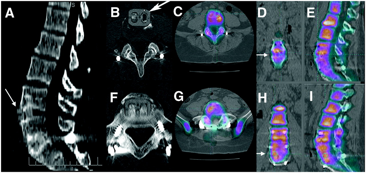
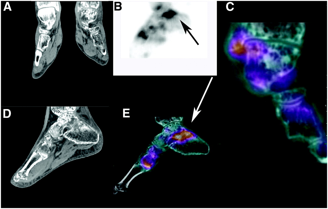
- FIGURE 13.
New onset of pain in left foot in patient with reflex sympathetic dystrophy. (A and D) Reformatted coronal slice through both ankles and sagittal slice of left ankle and foot showing profound demineralization of left ankle and foot. (B) Lateral MIP of 18F PET scan of left ankle with increased uptake (arrow) in subtalar joint. (C) CT and 18F fusion of normal uptake in ankle joint with minimal increase in uptake for medial malleolus. (E) Sagittal image of CT and 18F fusion showing abnormal uptake (arrow) in subtalar joint and first MTP joint. Close examination of CT images showed subtle insufficiency fractures for both areas. Fusion redirected attention to those areas where subtle insufficiency fractures were found on CT. Ankle joint is spared, as seen in rightmost fused coronal image.
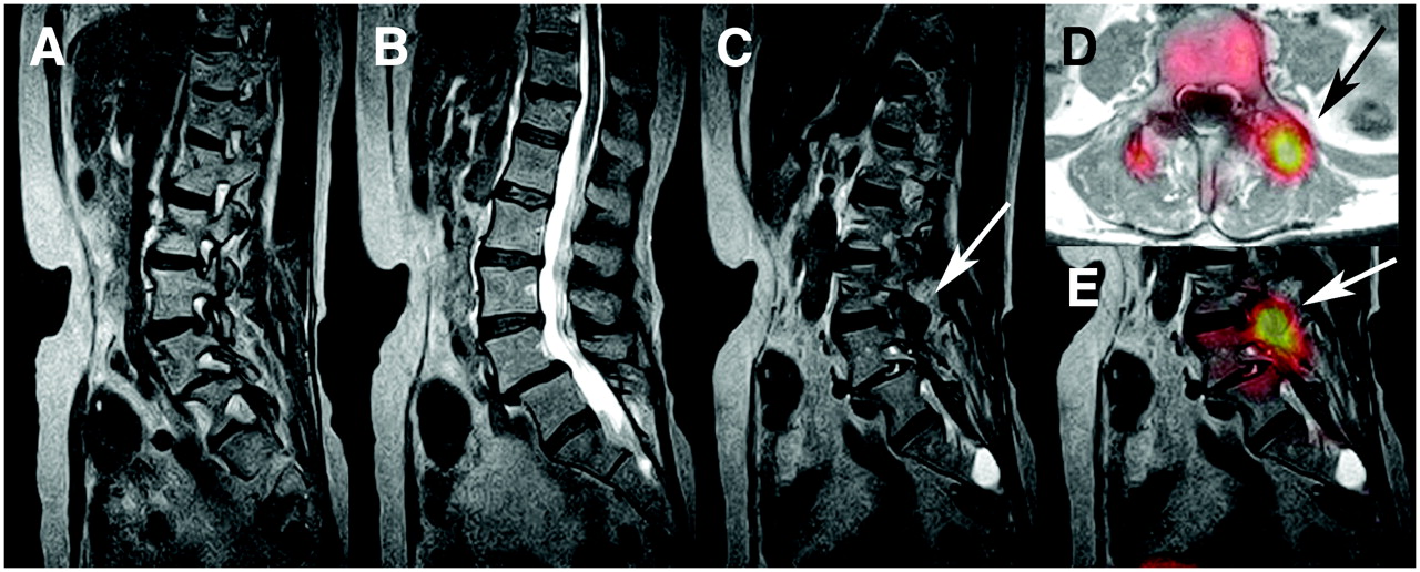
- FIGURE 14.
New-onset back pain in breast cancer patient with previous L4–L5 fusion. (A–C) Sagittal slices of T2-weighted MRI of lumbar spine without evidence of metastases. L4–L5 posterior fusion and facets are unremarkable on MRI. (C, D, and E) MRI, 18F, and MRI fusion showing, on transaxial slice, marked uptake in left L3–L4 facet from progressive arthritis (arrows). Combined imaging excluded malignancy. Directed facet block could be both diagnostic and therapeutic.
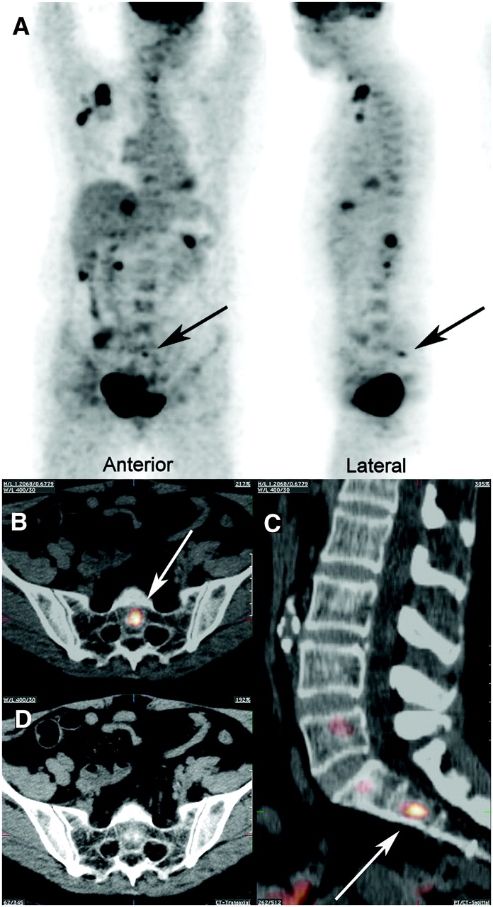
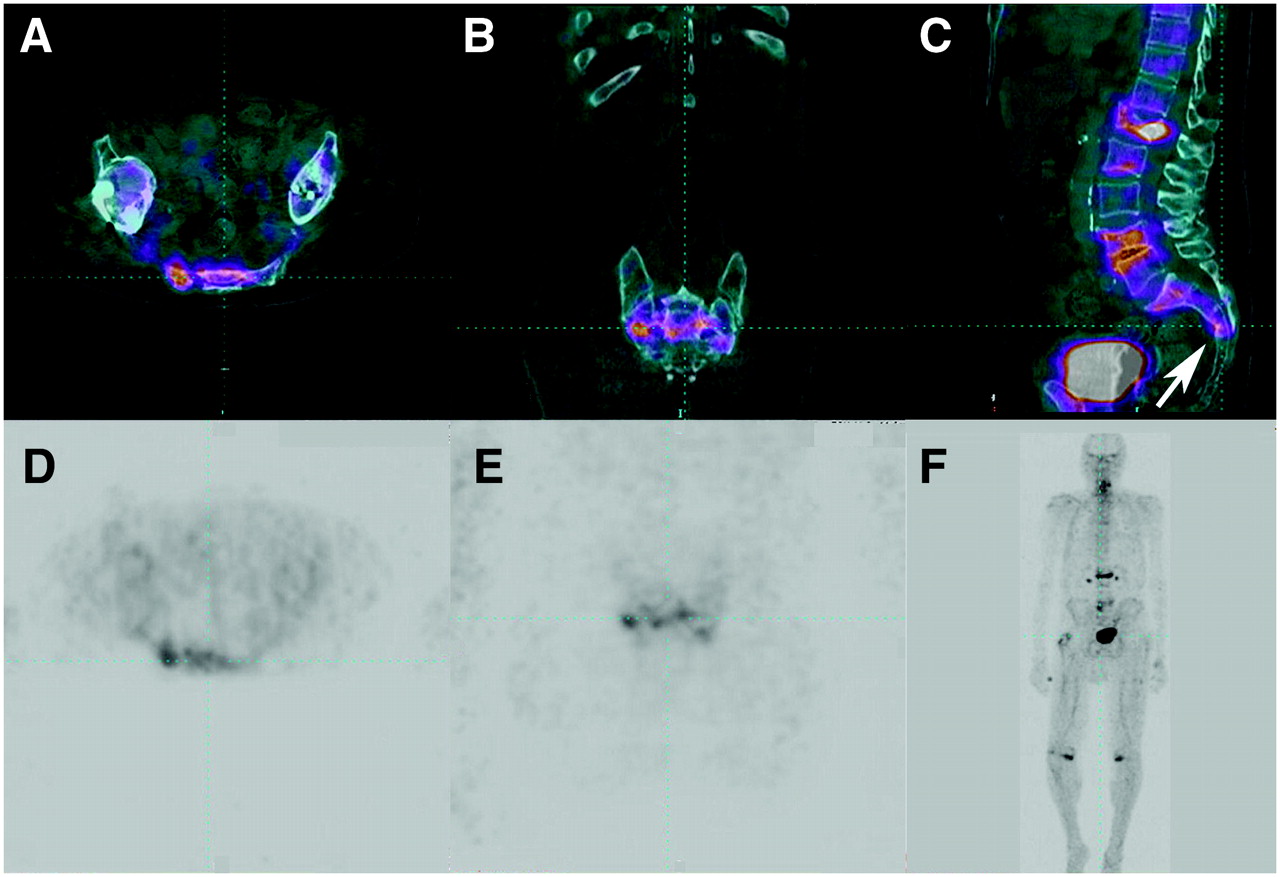
- FIGURE 15.
Increasing back pain and deep pelvic discomfort in elderly man. (A–C) Upper frames of CT and 18F fusion showing increased activity across sacrum and compression fractures of L1, L2, L4, and L5. Note buckle fracture of anterior wall of S3 (arrow). (D and E) Lower frames of delayed scan showing numerous areas of increased uptake in lumbar spine but ill-defined cluster of activity across sacrum. (F) MIP of 18F scan. “Connecting the dots” in sacrum identifies early sacral insufficiency fracture.
- FIGURE 16.
New-onset back pain with numerous compression fractures and kyphoplasties. (A) 3D CT of spine and pelvis showing numerous compression fractures. (B) Midsagittal slice through 3D column showing kyphoplasties and fractures. (C) 18F and CT fusion image showing several compression fractures, including new L1 superior endplate fracture and right rib fracture. (D) Fusion of 18F scan with CT scan showing readily identifiable correlation of vertebral bodies and areas of disease, including localization of compression fractures and facet disease. Normal activity around kyphoplasties (chalky white interiors of several vertebral bodies) may indicate adequate stabilization after cementing.
- FIGURE 17.
Failed front–back lumbar fusion: patient fell after recent surgery. (A) CT sagittal reformatted image shows that L4–L5 anterior interbody cassette has subluxed forward (arrow). L5–S1 cassette is in place. (B and C) Transaxial CT image of slipped cassette at L4–L5 (arrow) and fused PET bone/CT image of area of devitalized bone. (D and E) 18F and CT fusion in coronal and sagittal planes confirms devitalization of bone grafts at L4–L5. No activity crosses space between L4 and L5 (arrow in D). (F and G) CT and CT fusion of L5–S1. (H and I) Images showing that vital bone links L5 and S1 (arrow in H), unlike absence of activity across endplates at L4–L5. Improved resolution of 18F PET bone scanning allows interrogation of separate channels of cassettes.


Jump to section
Related Articles
Cited By...
- Bone-Targeted Imaging and Radionuclide Therapy in Prostate Cancer
- 18F-Fluoride PET in the Assessment of Malignant Bone Disease
- The Value of Observer Performance Studies in Dose Optimization: A Focus on Free-Response Receiver Operating Characteristic Methods
- Validation of a Paper Chromatographic Methodology as an Alternative for Determination of the Radiochemical Purity of Na18F
- Software Fusion: An Option Never Fully Explored