


Article Figures & Data
Figures
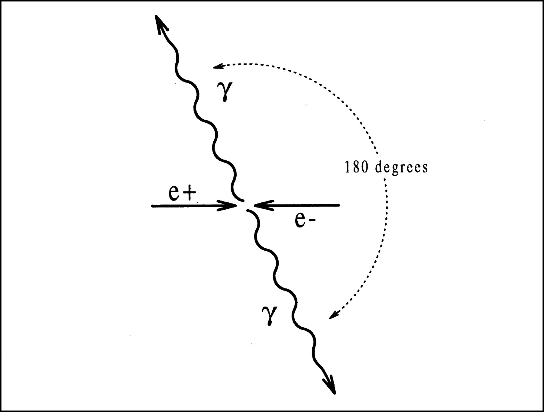
- FIGURE 1.
Diagram of electron–positron annihilation, producing 2 511 keV photons leaving in opposite directions.
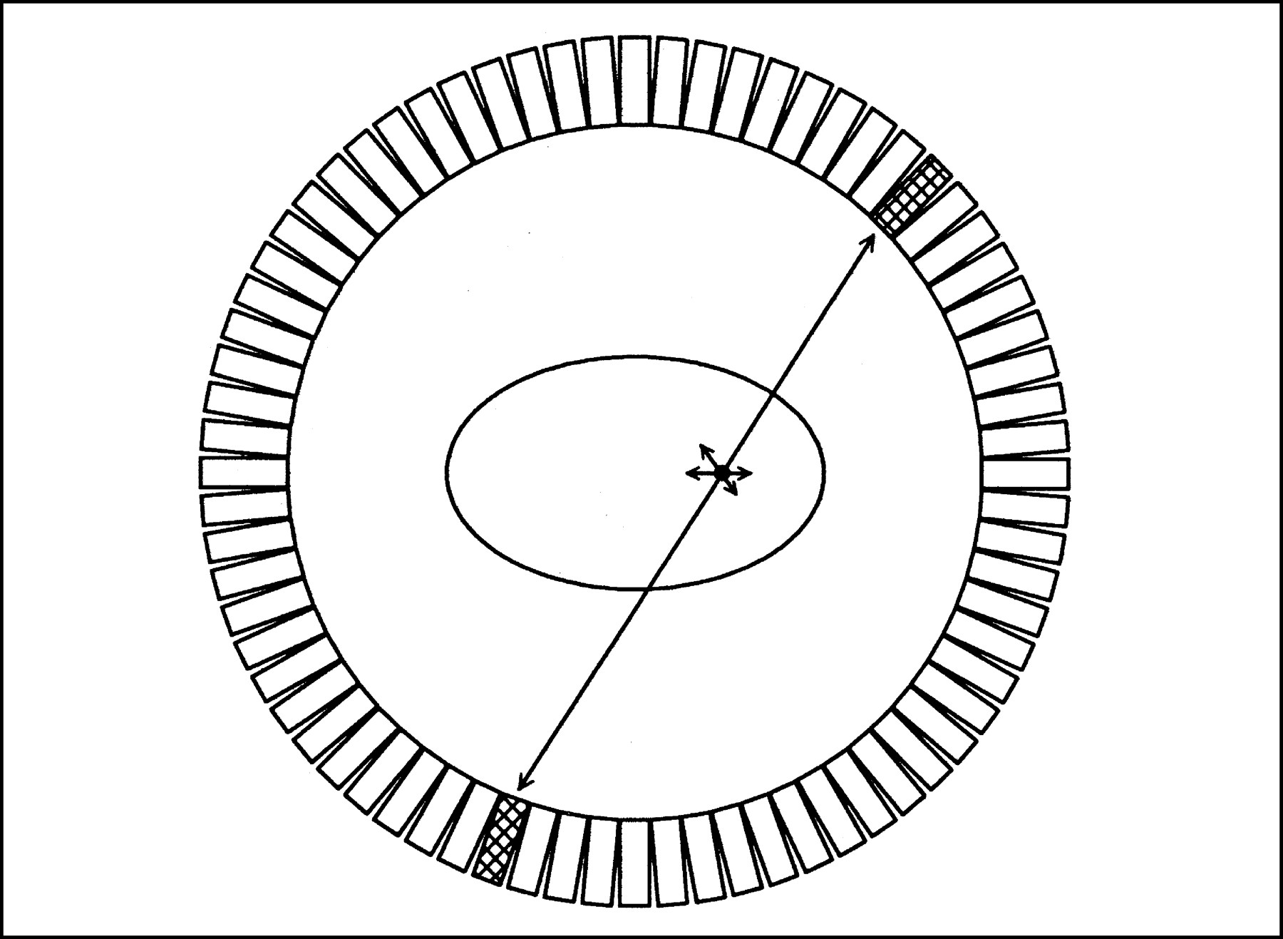
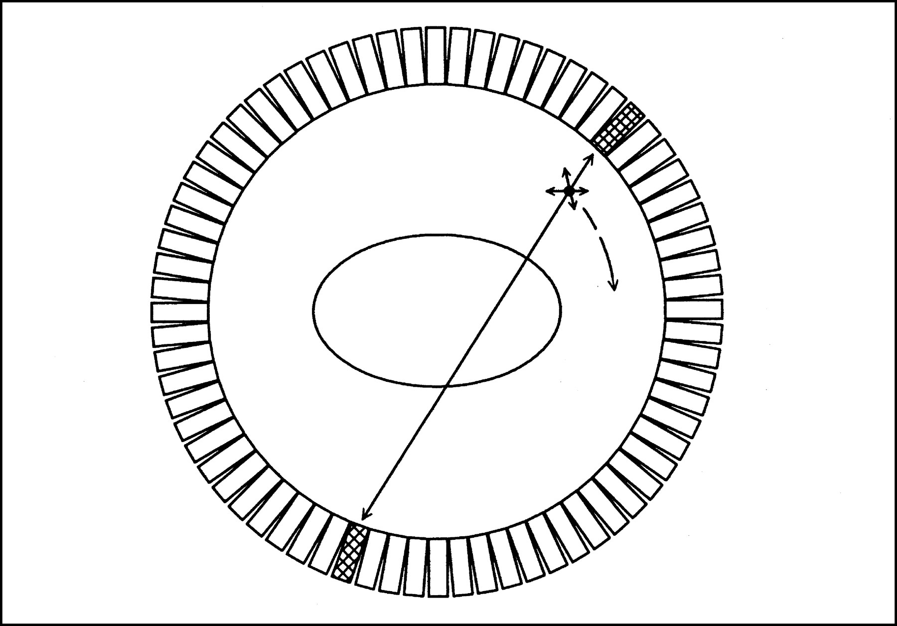
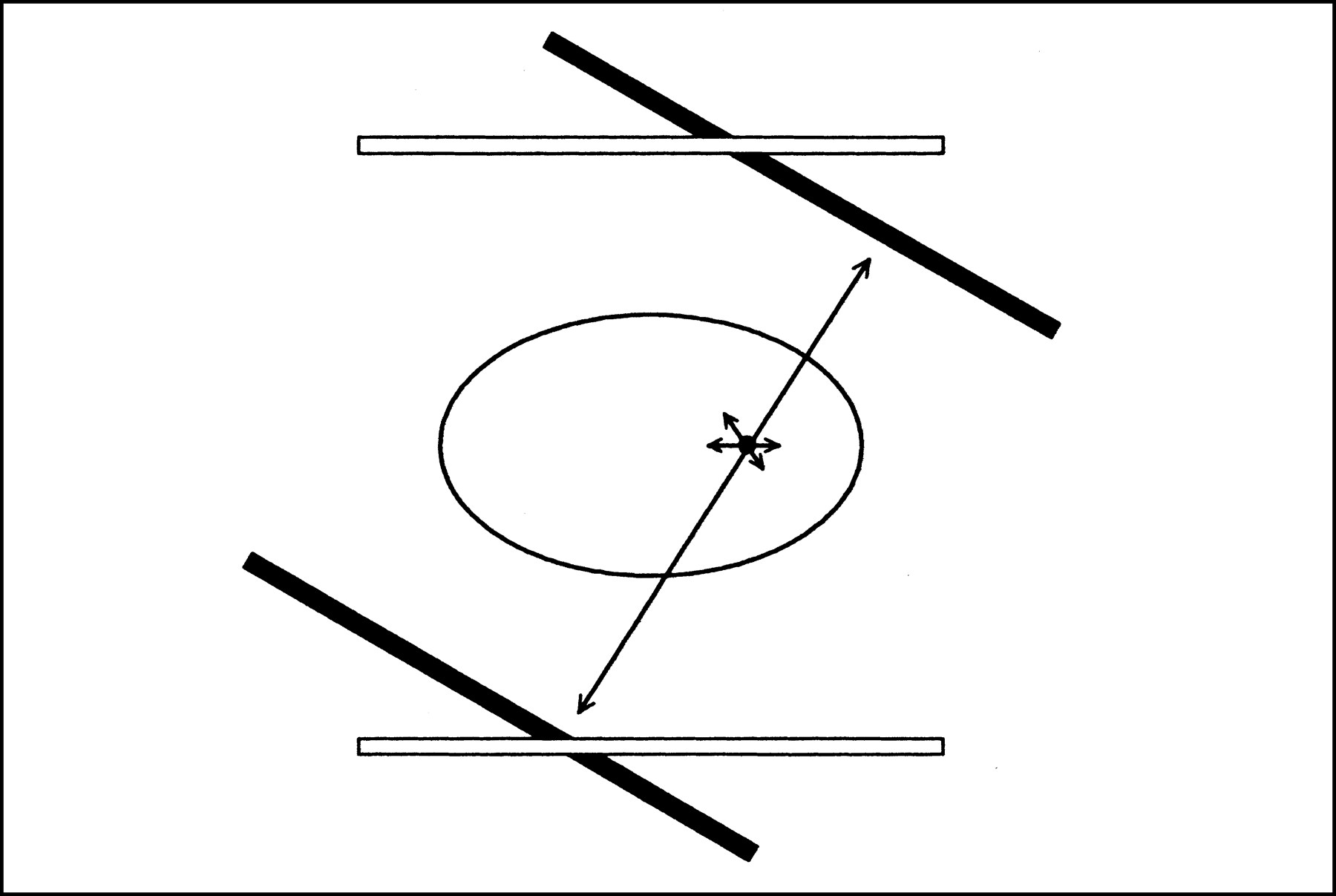
- FIGURE 2.
Coincidence event detected in ring PET scanner.
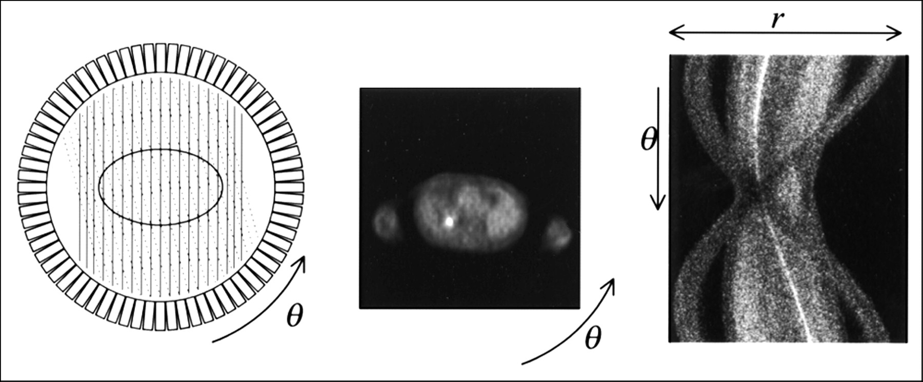
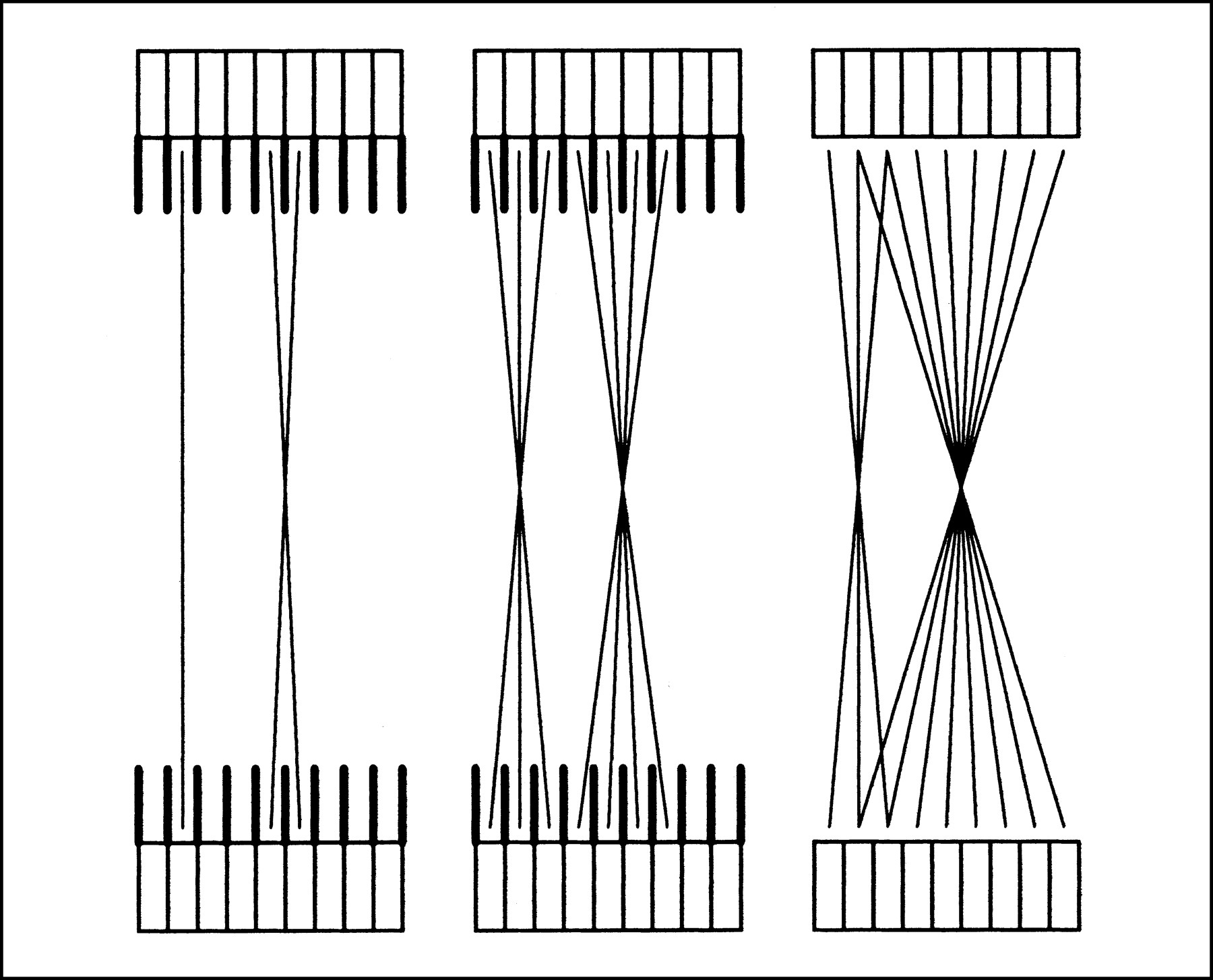
- FIGURE 3.
At left are detector pairs forming 2 projections, indicated by solid and dashed lines. In the middle is a cross-sectional radioactivity distribution from a patient. At right is the corresponding sinogram. The most notable features in the sinogram are the hot lesion, which is slightly off-center, and the arms, which are at a large radius when viewed at the first and last angles, but cross near the middle when viewed from the middle (horizontal) angles.
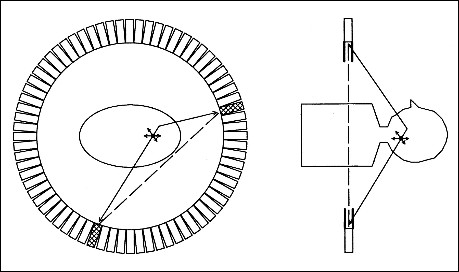
- FIGURE 4.
Scattered events. At left is in-plane scatter and at right is out-of-plane scatter, rejected by septa.
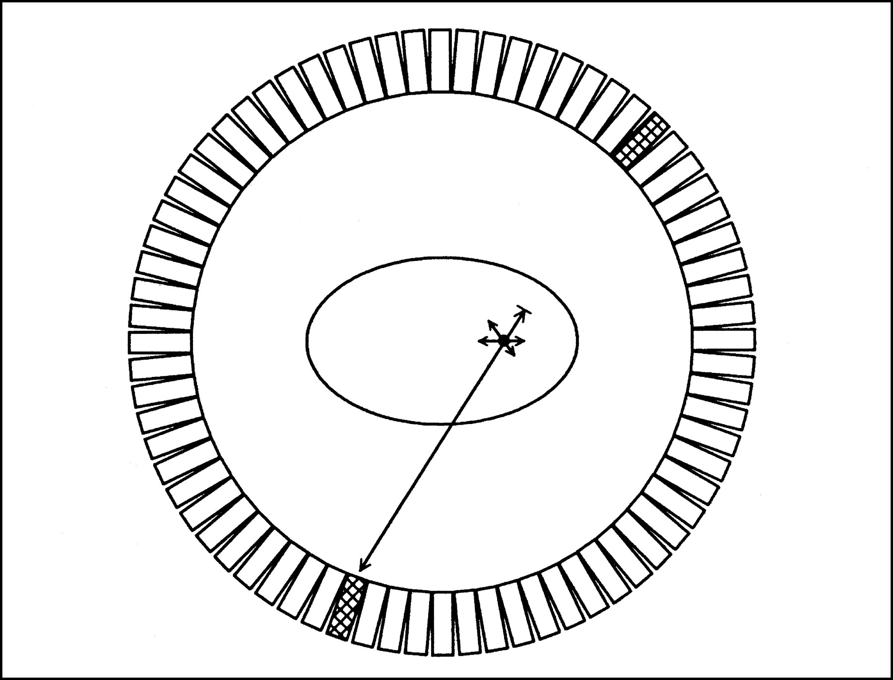
- FIGURE 5.
Attenuation. One of the photons is stopped or deflected before being detected.
- FIGURE 6.
Attenuation effects. At top are images without attenuation correction; at bottom are the same slices with attenuation correction. Noticeable artifacts in the noncorrected images include a bright exterior rim, bright lungs, nonuniform liver, and streaks from the heart.
- FIGURE 7.
Rotating source for transmission scan.
- FIGURE 8.
Image quality as a function of counts. The same phantom is imaged for various times, increasing approximately at a factor of 2. At top are images reconstructed with filtered back-projection. At bottom are images reconstructed with the ordered subsets algorithm (2).
- FIGURE 9.
Depth-of-interaction problem. Radiation entering the ring from a large radius could be detected in 1 of several detectors, resulting in degraded spatial resolution.
- FIGURE 10.
Multiring PET acquisition modes. At left are examples of simple 2D direct and cross planes. In the middle are extended 2D direct and cross planes for increased efficiency. At right is full 3D acceptance. The acceptance is greater for radiation in the middle of the axial FOV than for radiation near the end.
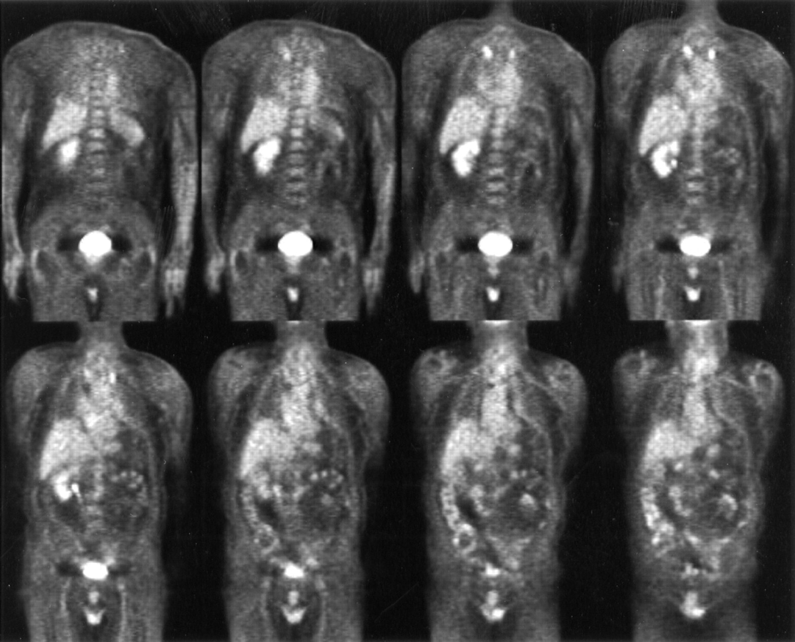
- FIGURE 11.
A whole-body F-18 fluorodeoxyglucose study from a dedicated PET scanner operating. Total scan time was 42 min.
- FIGURE 12.
An F-18 fluorodeoxyglucose brain tumor study from a dedicated PET scanner operating in 3D mode. Total scan time was 6 min.
- FIGURE 13.
Dual-head, rotating gamma camera operating in coincidence mode.
- FIGURE 14.
The use of septa for hybrid PET imaging. Solid lines represent detected events. Dashed lines represent different types of undetected events.
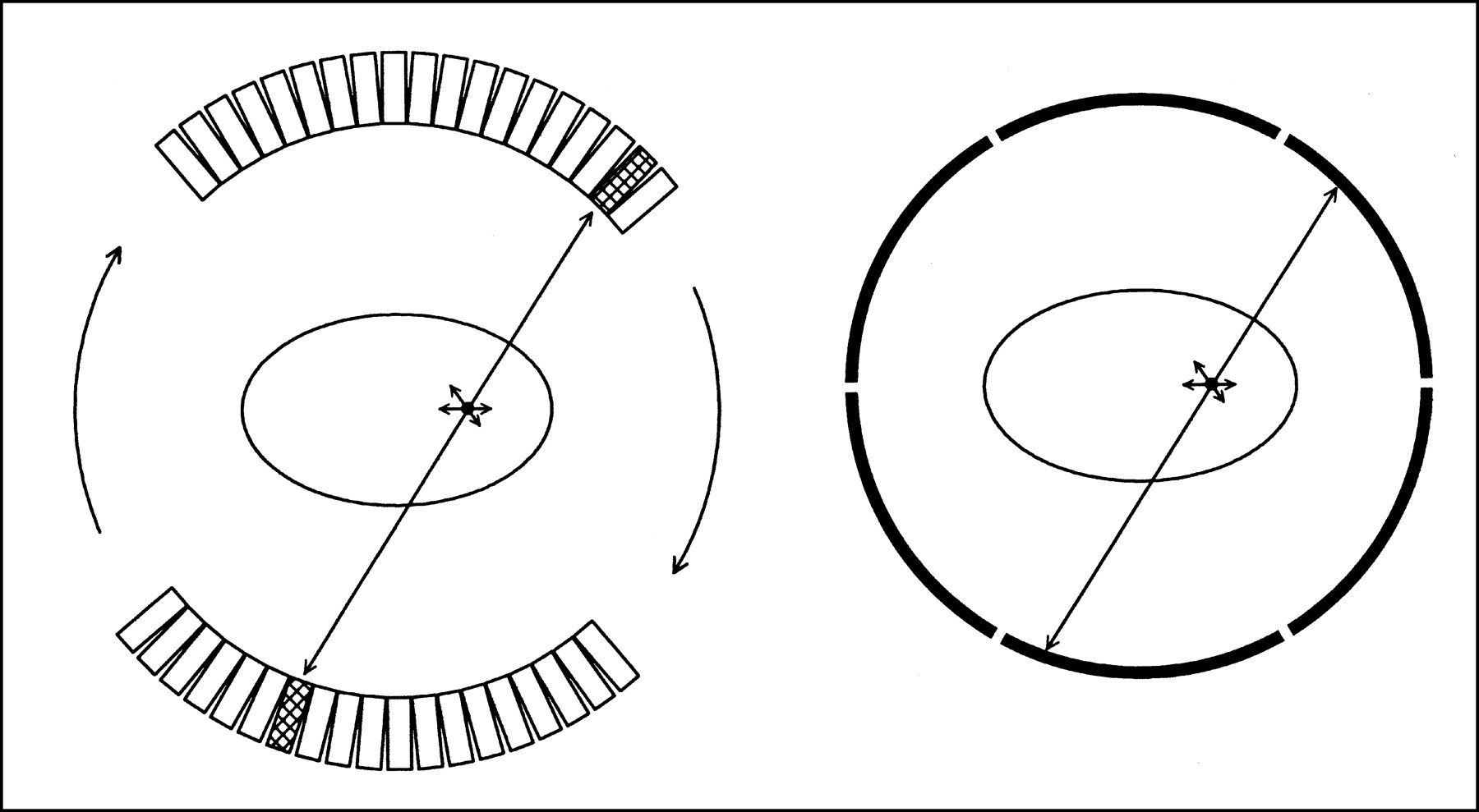
- FIGURE 15.
Two types of lower-cost dedicated PET scanners.


