


Abstract
SPECT produces nuclear medicine images using a 3-dimensional diagnostic tool that eliminates the superimposition of adjacent structures, thus providing improved disease localization. Another method of uniformity correction—to use the complete capabilities of this tool—is discussed and evaluated in this article. The conventional method of intrinsic uniformity correction accounts only for nonuniformities within the γ-camera, excluding the collimator. If SPECT image quality is related to overall camera performance, then using an extrinsic uniformity correction method rather than an intrinsic method will improve image quality. Methods: SPECT uniformity images were obtained using a SPECT phantom with application of intrinsic and extrinsic uniformity correction tables with 2 different γ-imaging systems. The image results were qualitatively assessed. Results: Even with acceptable nonuniformity analyses, significant ring artifacts within the intrinsic uniformity–corrected images are observed, whereas the artifacts are considerably less significant with the extrinsic uniformity correction and disappear completely in some of these images. Conclusion: Extrinsic uniformity correction may significantly improve the overall image quality by taking into account nonuniformities that arise from the collimator. This method will result in fewer image artifacts and improved image quality, thereby improving patient care.
SPECT allows for improved localization of radioactivity within a patient. Conventional or planar radionuclide imaging lacks the ability to localize the source of radioactivity within the deep structures of a patient because of the superimposition of overlying and underlying radiation. Because of the backprojection of data for image reconstruction, nonuniformities within the γ-camera present a significant problem for SPECT cameras (1). For each of the projections or angles for which the camera collects counts, nonuniformities will become apparent in the image and will back-project during reconstruction, thus creating a ring or bull's-eye artifact (2).
Within nuclear medicine laboratories, multiple quality control procedures are used to evaluate the proper function of the SPECT γ-camera, including daily uniformity floods, spatial resolution assessment, center-of-rotation assessment, and SPECT phantom evaluation. γ-camera uniformity is defined as the ability to produce a uniform image in response to a uniform source of γ-radiation, with acceptable percentage nonuniformity analyses in the 1%–3% range (3).
In addition to these quality control procedures, multiple correction techniques are available for addressing the inherent limitations of SPECT γ-cameras, including energy correction tables, linearity correction tables, center-of-rotation calibration, and uniformity correction tables (4,5).
The uniformity correction table is a uniformity correction method for a particular radionuclide that is acquired for a considerable number of counts (60–120 million) (1–3). This method uses the acquisition computer to evaluate the high-count flood and mean counts per pixel. The computer stores a pixel-by-pixel correction factor based on the variation of counts within the matrix from the correction flood. This uniformity correction table is applied to future acquisitions to correct for the nonuniformities within the camera (2,4).
Two methods may be used to acquire a uniformity correction table, intrinsic or extrinsic. Intrinsic uniformity correction tables correct for the nonuniformities within the detector head and electric components. This method excludes the collimator (4). Performed with a 99mTc point source, the point source provides a uniform flux of radiation to assess and correct for inherent detector head nonuniformities (6). Although this method produces a proper intrinsic uniformity correction table, the method does not compensate for possible collimator nonuniformities.
Accounting for nonuniformities within the collimator is an integral consideration for obtaining high-quality, clinical SPECT images. Nonuniformities of as little as 1% can cause disturbances within the images; therefore, every component of the SPECT γ-camera system must be considered for proper uniformity correction (7). For SPECT γ-cameras, the intrinsic method has progressed over the years to offer highly uniform and reliable intrinsic uniformity correction, but it still excludes the possible nonuniformities generated from the collimator.
Nonuniformities within the collimator arise from 2 possible sources. The first source of nonuniformity arises during the fabrication process itself. This nonuniformity is represented as the regional variation of photon transmission rates across the collimator, also termed efficiency. The variation of photon transmission rates is caused by nonuniform mechanical parts created during fabrication. Specifically, differences in septal thickness, the variation in sizes of the many channels, and deformation or damage created during fabrication can all contribute to system nonuniformities (8,9). In addition, there are various methods for collimator fabrication that affect the degree of nonuniformities.
The first method of fabrication consists of folding lead foil and stacking the lead strips on top of one another to form the collimator channels. This method produces septal wall thicknesses as small as 100 μm, which results in improved sensitivity; however, the thin septa are more susceptible to deformation and misalignment of the strips (10). Another method that helps compensate for some of the nonuniformities associated with folding lead foils is microcasting. For this method, hot lead is poured over collimator templates and the lead is cryogenically cooled (11). This fabrication process results in improved septal thickness uniformity and good angular alignment of septa. Microcast collimators are also structurally stronger than the conventional foil collimators; however, this method cannot produce septa thinner than 150 μm. (10) Microlinear technology is the final method of collimator fabrication. This method is similar to the foil method; however, the process uses automated 9-axis computer-controlled robotic movements to stack the lead foils (11). Regardless of which particular method of fabrication is used, nonuniformities within the collimator still exist and must be dealt with for proper uniformity correction.
The second source of nonuniformities that may present within a collimator are caused from day-to-day use of the camera. The collimator itself is deceptive because of its excessive weight and relative fragility (12). Because the collimator is placed directly next to a patient, impact from patient movement or the gantry is inevitable. Collimators made of lead foil sheets are also susceptible to mechanical or thermal stress (13). Septa deformation causes regional differences in collimator sensitivity, leading to nonuniformities. Significant obstruction of a channel can cause an artifact that will display as a cold spot; this artifact can be differentiated from a crystal artifact by the lack of a bright rim around the cold spot. Collimator damage that results in a crack will appear as an area of increased activity due to the leakage of counts (12,13). All these issues that result from normal use of the collimator are potential sources of nonuniformities. Visual inspection of the collimator offers limited evidence of this kind of wear and is no longer possible because of the application of patient crush-protection pads mounted on the front of the collimator (12).
Because of the possible sources of collimator nonuniformities, acquisition of an extrinsic uniformity correction table has been investigated. Acquisition of such a table can be problematic in cases of significant nonuniformity within the collimator arising from structural damage. Replacement of the damaged collimator may be warranted in these cases. Acquiring an extrinsic uniformity flood with the uniformity correction turned off will help demonstrate the degree of system nonuniformity and will help determine the integrity of the collimator.
Extrinsic uniformity correction tables require a source of radiation with a nonuniformity of 1% or less (1). 99mTc-water–filled sheet sources contain nonuniformities from air bubbles and incomplete mixing and are therefore not recommended for acquiring extrinsic uniformity correction tables. The use of a 57Co sheet source with less than 1% nonuniformity is recommended for this application. The 57Co sheet source is more reliable and more convenient than the water-filled source (1). The linear response of the crystal for the energy of 57Co (122 keV) will be roughly the same as for 99mTc (140 keV).
The uniformity of the 57Co sheet source is measured by the manufacturer and stated in the data sheet provided with a newly purchased source. Caution must be taken when using a new 57Co sheet source because of small amounts of 56Co and 58Co radionuclide contaminants, which can degrade source uniformity. The use of an older sheet source is recommended, because 56Co and 58Co have shorter half-lives than 57Co: 70–80 d versus 271 d, respectively (12).
We hypothesized that if SPECT image quality is related to overall camera performance, then using an extrinsic uniformity correction method rather than an intrinsic method will result in improved SPECT image quality.
MATERIALS AND METHODS
Verifying that the 57Co sheet source used to generate the extrinsic uniformity correction table is uniform on both sides is essential, especially for a dual-head system in which the uniformity correction table will be acquired simultaneously for each detector head. The following method does not determine the actual uniformity of the sheet source but helps determine whether the sheet source is uniform throughout and was performed for this investigation.
The sheet source was initially imaged in a single position for a total of 10 million counts, followed by uniformity analysis. The obtained percentage of nonuniformity takes into account both the nonuniformity of the γ-camera and the nonuniformity of the sheet source. After the acquisition of the 10-million-count image, the following images were obtained: a 2.5-million-count image of the source in the same position, a 2.5-million-count image of the source rotated 180°, a 2.5-million-count image of the source flipped over 180°, and a 2.5-million-count image of the source rotated 180°.
After all 4 images were obtained, the images were summed to make a collective 10-million-count image. Uniformity analysis was performed to determine the percentage of nonuniformity in the summed image. The resulting percentage was within a few tenths of a percentage point of the 10-million-count image, thus verifying that the source provided by the vendor was uniform throughout.
Again, the vendor provides the percentage nonuniformity of the sheet source itself. Most vendors will provide a sheet source of less than 1% nonuniformity if asked. Some vendors will even measure and guarantee uniformity of both sides of the sheet source. If this is the case, then the above steps to ensure uniformity of both sides of the source can be omitted.
Two different γ-cameras were used to demonstrate the importance of extrinsic uniformity corrections, a Vertex Ultra (ADAC) and an Infinia (GE Healthcare). Steps were performed to ensure that the collimator was the most significant source of nonuniformity. These steps were performed on both camera systems before acquisition of new uniformity correction tables. The gain of each photomultiplier tube was adjusted so that all tubes were balanced. After photomultiplier tube adjustment, a new energy correction table was acquired for 99mTc, as well as a new linearity (spatial) correction table for each detector head. Next, the uniformity correction tables were acquired. Also, the center-of-rotation correction tables were updated after the acquisition of new uniformity correction tables per protocol. Table 1 demonstrates the parameters used for acquiring the 400-million-count uniformity correction tables. After the acquisition of uniformity correction tables, intrinsic and extrinsic uniformity analysis was performed to evaluate the percentage nonuniformity for each detector head on both cameras—percentages that were well within acceptable limits (Table 2).
Parameters for Acquiring Uniformity Correction Table
Percentage Nonuniformity Analysis for Each Detector Head for Both Cameras
After the uniformity correction and uniformity analysis, SPECT was performed with a Deluxe Jaszczak SPECT Phantom with a low-energy high-resolution collimator. Table 3 lists the parameters used for acquiring SPECT images of the phantom for the 2 camera systems. The phantom was prepared by adding 99mTc to the water-filled cylinder. The phantom was allowed to reach uniformity for 5–6 h, and at the time of acquisition, the phantom contained approximately 740–925 MBq (20–25 mCi) of 99mTc. SPECT was performed on the Infinia with the intrinsic uniformity correction table selected. Although the phantom is a circular shape, because of table geometry an elliptic orbit was used to allow for the least distance between the phantom and detector heads. The distance from the phantom to the detector head was approximately 5–10 cm for various angles of the elliptic orbit.
Dual-Head Camera Parameters for SPECT Phantom Acquisition
Once the acquisition was completed, the gantry was reset and another acquisition was performed with the extrinsic uniformity correction table selected on the same camera. No activity was added to the phantom, nor was the phantom moved between the acquisitions.
The same procedure was followed for the Vertex camera. The back-to-back acquisitions ensured that camera performance would be relatively stable between acquisitions.
The acquired data from the 2 cameras was sent to a Xeleris (GE Healthcare) processing station to ensure consistency in processing. The same processing parameters were used for SPECT processing of the 4 datasets. The data were prefiltered using parallel filtered backprojection with a Butterworth filter and postfiltered using ordered-subset expectation maximization/maximum likelihood expectation maximization iterative reconstruction with 5 iterations. The Butterworth filter consisted of a cutoff of 0.45 cycles/cm and an order of 7.0 cycles/cm. Uniform attenuation correction was applied using an attenuation coefficient of 0.10 to account for the attenuation of 99mTc in water.
RESULTS
The percentage nonuniformity analysis for each camera is presented in Table 2. The nonuniformity for each detector head was considered acceptable, ranging from 1% to 2.5%.
The SPECT image data are presented in Figures 1 and 2. The intrinsic uniformity–corrected slices (A) of the phantom are arranged next to the corresponding extrinsic uniformity–corrected slices (B) for each camera to reveal any nonuniformity artifacts. The ring artifacts are observed in both Figure 1A and Figure 2A. Figure 2 demonstrates more significant ring artifacts within the intrinsic uniformity–corrected images.
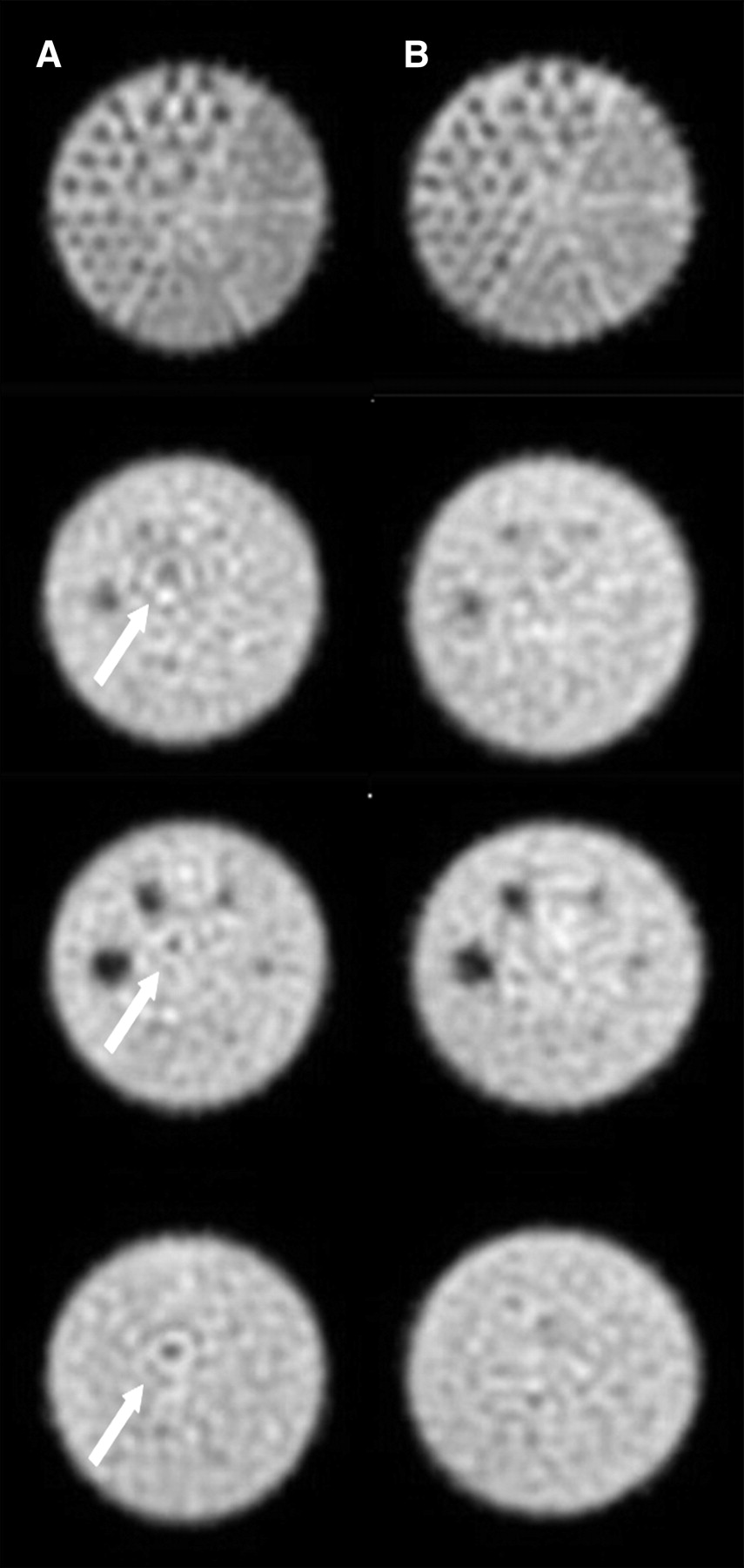
Phantom images from Vertex: intrinsic uniformity corrected images (A) and extrinsic uniformity corrected images (B). Arrows indicated visualized ring artifacts. A color version of this figure is available as a supplemental file at http://tech.snmjournals.org.
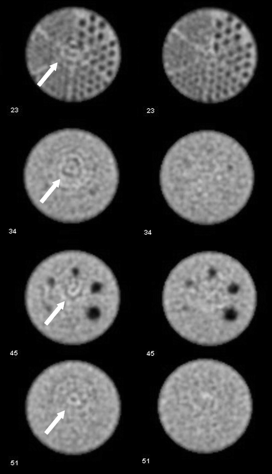
Phantom images from Infinia: intrinsic uniformity corrected images (A) and extrinsic uniformity corrected images (B). Arrows indicated visualized ring artifacts. A color version of this figure is available as a supplemental file at http://tech.snmjournals.org.
One can observe that the ring artifacts are considerably less significant for the extrinsic uniformity–corrected images and disappear completely in most images.
DISCUSSION
Replacing intrinsic uniformity correction with extrinsic uniformity correction in the clinical setting to account for nonuniformities within the total γ-camera system should be considered and evaluated. Comparison of the image data clearly demonstrates the effectiveness of extrinsic uniformity correction, versus intrinsic uniformity correction, in eliminating nonuniformities from the detector and collimator. Although these nonuniformities may be considered acceptable using daily nonuniformity analysis, the impact on SPECT images is still noticeable.
Future investigations should be conducted to determine when collimator replacement is recommended instead of extrinsic uniformity correction. Newer fabrication techniques provide better-quality collimators, but defects may persist during manufacturing or daily use. This point is illustrated in the 2 figures of this study. The nonuniformities that are expressed as ring artifacts come from nonuniformities within the collimator. The SPECT phantom images from the Vertex camera, shown in Figure 1, are from an older camera that uses collimators made from folding lead foil. These types of collimators can be more prone to defects, but the images show fewer ring artifacts than are seen in Figure 2. In Figure 2, the Infinia uses a collimator that was fabricated using the microcasting method. The ring artifacts in these images are more significant. This finding is most likely due to greater damage to the collimators on the newer camera, but further analysis is needed.
These 2 figures illustrate the importance of total system performance and of taking into consideration the nonuniformities from the collimator with extrinsic uniformity corrections.
CONCLUSION
To begin to truly use the full benefits SPECT can provide, technologists need to improve the overall uniformity within the entire γ-camera. Extrinsic uniformity correction has the ability to significantly improve the overall uniformity by taking into account nonuniformities that arise from the collimator. This method improves image quality.
Acknowledgments
No potential conflict of interest relevant to this article was reported.
Footnotes
Published online Jul. 27, 2011.
REFERENCES
- Received for publication November 15, 2010.
- Accepted for publication April 15, 2011.


Jump to section
Related Articles
Cited By...
- No citing articles found.